Home
>
Products > Laser Rangefinder Module > 1535nm Laser Range Finder Module > 5km Eye-safe Laser Rangefinder Module(LRF)


")
5km Eye-safe Laser Rangefinder Module(LRF)
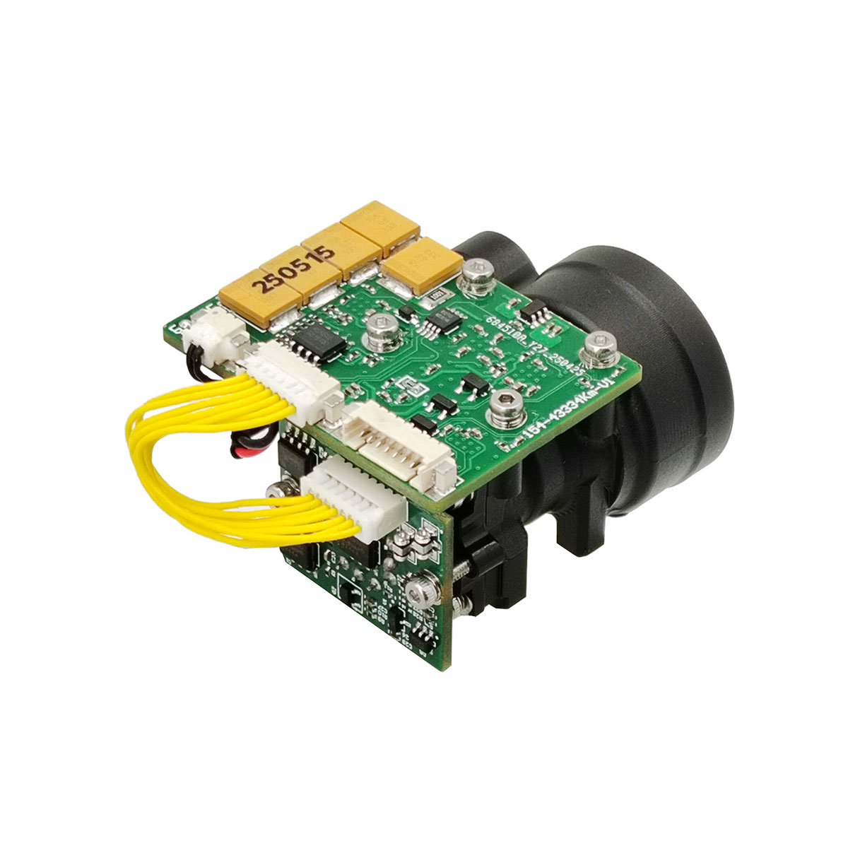
STA-B50MX is a human eye-safe laser distance measurement module, which can detect the target distance and transmit the measured distance to the upper computer through serial communication. Visibility ≥ 12km, target reflectivity ≥ 0.3, humidity ≤ 80%, the vehicle (2.3m × 2.3m NATO target) ranging distance ≥5km.
Send Inquiry
Product Description
Main functions
(1) Single ranging and continuous ranging;
(2) Responding to laser ranging commands, and can stop ranging at any time according to the stop command;
(3) Output distance data and status information once per pulse during distance measurement;
(4) It can report the cumulative number of transmitted laser pulses (no loss of power down);
(5) Distance selection, front and rear target indication;
(6) Self-test function.
Product performance index
| Item | Technical parameter | Instruction |
| Model | STA-B50MX | |
| Working wavelength | 1535±5nm | |
| Eye safety | Class 1 (IEC 60825-1) | |
| Receiving Aperture | Φ25mm | |
| Emission aperture | Φ10mm | |
| Ranging capability | 30-8000m | |
| Ranging range | ≥10000m | MAX Range, Reflectivity: 0.9, observer visibility 25km |
| ≥7000m | Large Building targets, Reflectivity: 0.6, observer visibility 20 km | |
| ≥5000m | NATO target | |
| ≥3000m | Human target | |
| ≥1500m | UAV target | |
| Mini Range | 30m |
|
| Multi-target detection | Up to 3 target |
|
| Range resolution | 30m |
|
| Ranging accuracy | ±1m |
|
| Ranging frequency | 1~10Hz adjustable |
|
| Accuracy rate | ≥98% |
|
| False alarm rate | 1% |
|
| Divergence angle | ≤0.5mrad |
|
| Communication Interface | RS422 | TTL/RS232 Interface can be customised |
| Voltage | DC9~32V |
|
| Power consumption | ≤1.2W(@1hz) | Working power |
| ≤5W@12V | Peak power | |
| 0.1W | Standby power (Connect POWER-ON) | |
| Laser optical axis stability | ≤0.05mrad |
|
| Parallel error | ≤0.3mrad | Parallelism error of optical axis to mounting reference |
| Mechanical Shock | 75g, 1ms |
|
| Working temperature | -40℃~+70℃ |
|
| Storage temperature | -55℃~+75℃ |
|
| Reliability | MTBF ≥ 1500h |
|
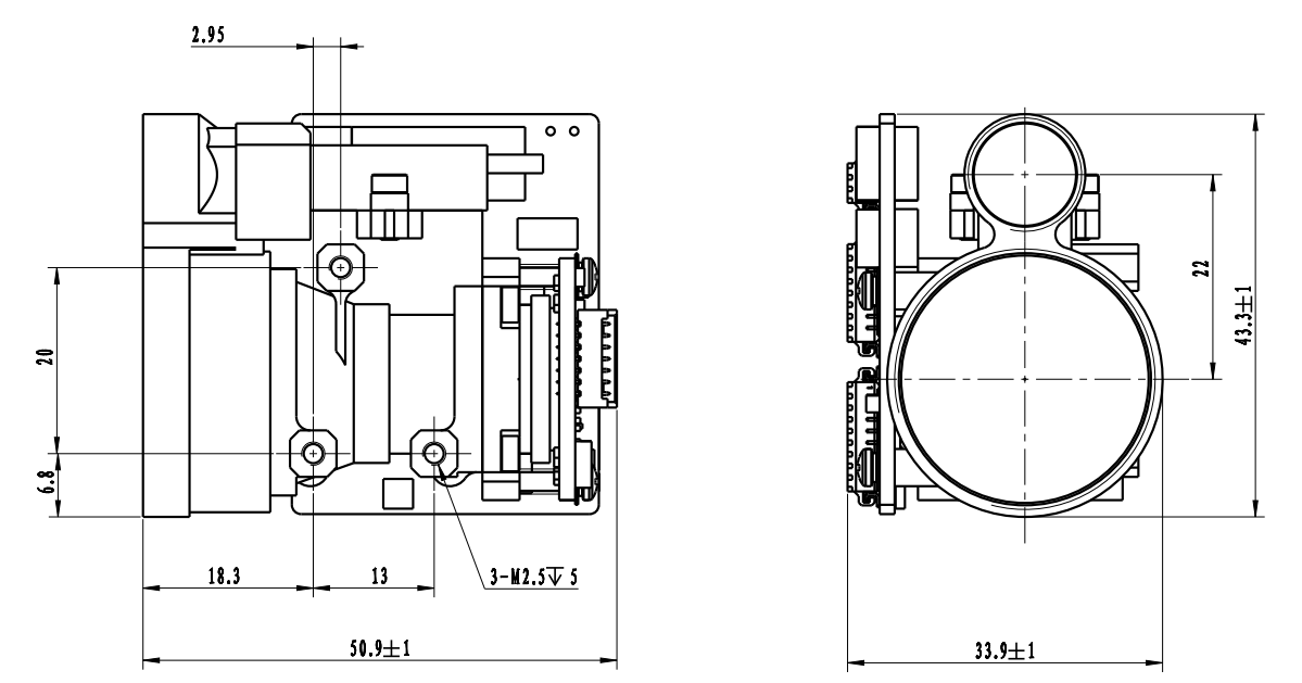
| Size | ≤50x32x43.5mm |
|
| Weight | ≤75g |
|
| Main Function | First and last target ranging, Multi-target ranging, Distance selectivity | |
Notes:
1) NATO target size 2.3 m × 2.3 m; Human target size 0.5 m × 1.7 m; UAV target size 0.2 m × 0.3 m; Reflectivity 30%, Humidity≤80%,observer visibility≥ 12km
Structure installation interface
External Interface
| Pin | Definition | Function | Notes |
| 1 | RX+ | RS422 Receiver + | Blue |
| 2 | RX- | RS422 Receiver - | Green |
| 3 | TX- | RS422 Transmission - | Purple |
| 4 | TX+ | RS422 Transmission + | Yellow |
| 5 | GND | Communication ground wire | White |
| 6 | VEE | Power supply + | Red |
| 7 | GND | Power supply - | Black |
| 8 | PWR EN | / | Ash |
External Interface
OEM/ODM ranging modules and custom solutions
The B50MX is designed for system integrators looking for a convenient, powerful and compact laser ranging solution. It provides reliable performance in a wide range of applications.
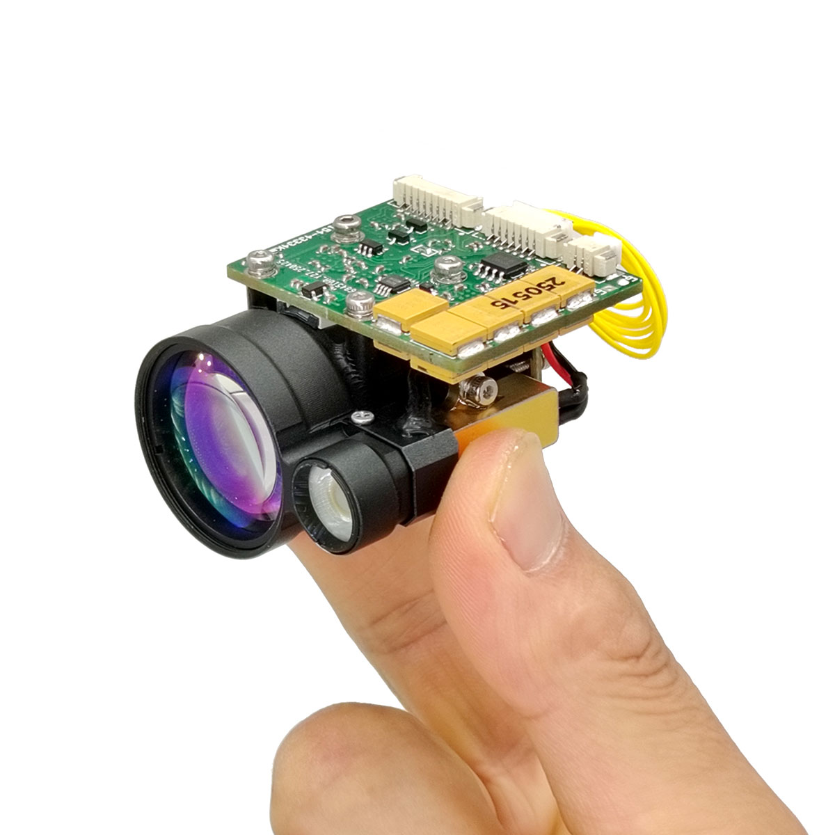
It is very small, ultra-light, has low power consumption and can be measured over a long distance. It is suitable for handheld devices (thermal imaging), weapon mounting applications, portable systems and lightweight sensor suites and unmanned aerial vehicles or UGVs.
The B50MX is designed for system integrators looking for a convenient, powerful and compact laser ranging solution. It provides reliable performance in a wide range of applications.
It is very small, ultra-light, has low power consumption and can be measured over a long distance. It is suitable for handheld devices (thermal imaging), weapon mounting applications, portable systems and lightweight sensor suites and unmanned aerial vehicles or UGVs.
Communicating protocol
1. Transmission protocol: asynchronous serial communication;
2. Port rate: 115200;
3. Data bits: 10bits: one start bit, 8 data bits, one stop bit, invalid verification;
4. Data structure: The data consists of the header byte, command part, data length, parameter part and check byte;
5. Communication mode: the master control sends control commands to the ranging machine, and the ranging machine receives and executes the instructions. In the ranging state, the ranging machine sends data and status of the ranging machine back to the upper computer according to the ranging cycle. The communication format and command content are shown in the following table.
A) Main control sends
The format of the message to be sent is as follows:
| STX0 | CMD | LEN | DATA1H | DATA1L | CHK |
Table 2 Format description of the message sent
| order number | name | explain | code | remarks |
| 1 | STX0 | Message start flag | A5(H) |
|
| 2 | CMD | CW | See table 3 |
|
| 3 | LEN | DL | The number of all bytes except the start mark, command word, and checksum |
|
| 4 | DATAH | parameter | See table 3 |
|
| 5 | DATAL |
|
||
| 6 | CHK | XOR verification | Except for the valid byte, all other bytes are XORed |
|
The command is described as follows:
Table 3 Description of commands and data words sent by the master to the ranging machine
Table 3 Description of commands and data words sent by the master to the ranging machine
| order number | CW | function | data byte | remarks | length | Example code |
| 1 | 0x00 | cease | DATAH=00(H)DATAL=00(H) | The rangefinder stops measuring | Six bytes | A5 00 02 00 00 A7 |
| 2 | 0x01 | Single ranging | DATAH=00(H)DATAL=00(H) |
|
Six bytes | A5 01 02 00 00 A6 |
| 3 | 0x02 | Continuous ranging | DATAH=XX(H)DATAL=YY(H) | DATA describes the ranging period, in ms | Six bytes | A5 02 02 03 E8 4E (1Hz ranging) |
| 4 | 0x03 | self-checking | DATAH=00(H)DATAL=00(H) |
|
Six bytes | A5 03 02 00 00 A4 |
| 5 | 0x04 | Set the closest distance to the selection | DATAH=XX(H)DATAL=YY(H) | DATA describes the blind zone value, unit 1m | Six bytes | A5 04 02 00 64 C7(100m is the closest distance) |
| 6 | 0x06 | Cumulative number of light output queries | DATAH=00(H)DATAL=00(H) | Cumulative number of light output queries | Six bytes | A5 06 02 00 00 A1 |
| 7 | 0x11 | APD power is on | DATAH=00(H)DATAL=00(H) |
|
Six bytes | A5 11 02 00 00 B6 |
| 8 | 0x12 | APD power is off | DATAH=00(H)DATAL=00(H) |
|
Six bytes | A5 12 02 00 00 B5 |
| 9 | 0xEB | Number query | DATAH=00(H)DATAL=00(H) | Number query | Six bytes | A5 EB 02 00 00 4C |
a)Main control receives format
The format of the received message is as follows:
The format of the received message is as follows:
| STX0 | CMD | LEN | DATAn | DATA0 | CHK |
Table 4 Format description of received messages
| order number | name | explain | code | remarks |
| 1 | STX0 | Message start flag 1 | A5 (H) |
|
| 2 | CMD_JG | Data command word | See table 5 |
|
| 3 | LEN | DL | The number of all bytes except the start mark, command word, and checksum |
|
| 4 | Dn | parameter | See table 5 |
|
| 5 | D0 |
|
||
| 6 | CHK | XOR verification | Except for the valid byte, all other bytes are XORed |
|
Main control receiving status description:
Table 5 describes the data word sent by the rangefinder to the master controller
Table 5 describes the data word sent by the rangefinder to the master controller
| order number | CW | function | data byte | remarks | overall length |
| 1 | 0x00 | cease | D1=00(H)D0=00(H) |
|
Six bytes |
| 2 | 0x03 | self-checking | D8 ~D1 | D8-D7: -5V voltage, unit 0.01V.D6-D5: Blind spot value, unit 1mD4: APD high voltage value, unit V;D3: char type, indicating APD temperature, unit: degrees Celsius;D2-D1: +5V voltage, unit 0.01V | 12 bytes |
| 3 | 0x04 | Distance to the nearest access setting, unit m | D1 D0 | DATA describes the nearest distance value, unit 1m;Start high and end low | Six bytes |
| 4 | 0x06 | Cumulative number of light output queries | D3~D0 | DATA expresses the number of lights, 4 bytes, with the high byte first | Seven bytes |
| 5 | 0x11 | APD power is on | D1=00(H)D0=00(H) | APD power is on | Six bytes |
| 6 | 0x12 | APD power off | D1=00(H)D0=00(H) | APD power is off | Six bytes |
| 7 | 0xED | Working overtime | 0x00 0x00 | The laser is under laser working protection and cannot be measured. | Six bytes |
| 8 | 0xEE | Effectiveness errors | 0x00 0x00 |
|
Six bytes |
| 9 | 0XEF | Serial port communication timeout | 0x00 0x00 |
|
Six bytes |
| 10 | 0x01 | Single range measurement (single target, zero for the second and third targets, zero for the third target at the beginning and end of the target) | D9D8 D7 D6D5 D4 D3D2 D1 D0 | D8-D6 first target distance (unit 0.1m)D5-D3 distance to the second target (unit: 0.1m)D2-D0 third target distance (unit 0.1m)3. Goals are from near to farD9 (bit7-bit0) flag byte:D9 is the 7th position indicating the main wave; 1: there is a main wave, 0: no main wave.D9 is the 6th position indicating echo; 1: there is echo, 0: no echoD9 The fifth position indicates the laser status; 1: normal laser, 0: laser faultD9 is the fourth bit of the timeout flag, 1: normal, 0: timeoutD9 is invalid at the 3rd position (set to 1);D9 The second position indicates the APD status; 1: normal, 0: errorD9 is the first position to indicate whether there is a previous target; 1: there is a previous target, 0: no previous target (target in the blind area).D9 The 0th bit indicates whether there is a subsequent target; 1: there is a subsequent target, 0: no subsequent target (the target after the main target is the subsequent target) | 14 bytes |
| 11 | 0x02 | Continuous ranging (single target, zero for the second and third targets, zero for the third target at the beginning and end of the target) | D9 D8 D7 D6D5 D4 D3D2 D1 D0 | D8-D6 first target distance (unit 0.1m)D5-D3 distance to the second target (unit: 0.1m)D2-D0 third target distance (unit 0.1m)3. Goals are from near to farD9 (bit7-bit0) flag byte:D9 is the 7th bit to indicate the main wave; 1: there is a main wave, 0: no main wave.D9 is the 6th position indicating echo; 1: there is echo, 0: no echoD9 The fifth position indicates the laser status; 1: normal laser, 0: laser faultD9 is the fourth bit of the timeout flag, 1: normal, 0: timeoutD9 is invalid at the 3rd position (set to 1);D9 The second position indicates the APD state; 1: normal, 0: errorD9 is the first position to indicate whether there is a previous target; 1: there is a previous target, 0: no previous target (target in the blind area).D9 The 0th bit indicates whether there is a subsequent target; 1: there is a subsequent target, 0: no subsequent target (the target after the main target is the subsequent target) | 14 bytes |
| 12 | 0xEB | Number query | D17…… D0 | D17 D16 D15 D14 D13 D12 Whole machine model codeD11D10 Product numberD9 D6 software versionD5 D4 APD numberD3 D2 Laser numberVersion D1 of FPGA | 22 bytes |
| Note: ① Undefined data byte/bit, default is 0; | |||||
Hot Tags: 5km Eye-safe Laser Rangefinder Module(LRF), Manufacturers, Suppliers, Factory, China, Made in China, Customized, High Quality
Related Category
905nm Laser Range Finder Module
1535nm Laser Range Finder Module
1570nm Laser Range Finder Module
1.54um Laser Rangefinder Module
1064nm Laser Target Designator
Anti drone ststem module
Ranging Lidar Module
Send Inquiry
Please feel free to give your inquiry in the form below. We will reply you in 24 hours.