Home
>
Products > Laser Rangefinder Module > 1535nm Laser Range Finder Module > 9km Range Finder Module


9km Range Finder Module
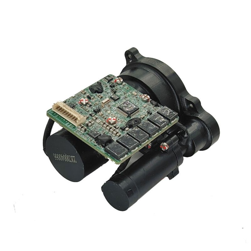
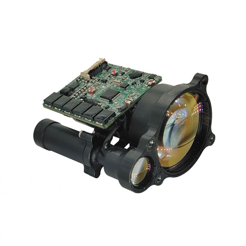
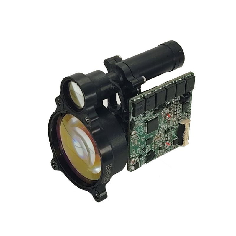
STA-D0912Y 9km Range Finder Module adopts the 1535nm erbium glass laser module independently developed by Jioptics, which has the characteristics of low power consumption, compact structure, high precision, long measuring distance and human eye safety.
Send Inquiry
Product Description
Maximum measuring range: 9000m (vehicle) 12000 m (wall)
Ranging accuracy ±1m
Measurement accuracy ≥ 98%
Weight ≤102g
Ranging accuracy ±1m
Measurement accuracy ≥ 98%
Weight ≤102g
9km Range Finder Module features
1. Integrated design of the whole structure, shock resistance, vibration resistance, high reliability, strong environmental adaptability;
2. The use of unique erbium glass laser integrated configuration design and end-face multi-point sealing installation, high durability, long working life, eye safety;
3. The internal interfaces of the circuit all adopt the welding wire direct connection process, which is firm and reliable, which can avoid the short circuit or poor contact caused by the loosening, oxidation and water vapor of the connector, and improve the reliability and life of the product.
Product performance index
| Item | Index | |
| Model | STA-D0912Y | |
| Operating wavelength | 1535nm ±10nm | |
| Ranging range | 80m-12000m | |
| Ranging capability | 16000m | Typical target,visibility ≥ 25km |
| 12000m | Large target, visibility ≥ 25km | |
| 9000m | Visibility ≥ 25km, target with 0.3 reflectivity for 2.3m × 4.6m vehicles | |
| Humidity | ≤ 80% | |
| Ranging accuracy | ±1m | |
| Accuracy rate | ≥98% | |
| Range resolution | ≤50m | |
| Divergence angle | ≤0.5mrad | |
| Ranging frequency | Once,1hz,5hz | |
| Size | ≤66mm×59mm×42mm | |
| Voltage | 5V~14V | |
| Working power consumption | Average power consumption: ≤ 3W | |
| Standby power consumption | ≤0.01W | |
| Working temperature | -40℃~+60℃ | |
| Storage temperature | -55℃~+70℃ | |
| Weight | ≤102g | |
Structure installation interface


Electrical Interface
The upper computer end realizes the cross-linking test with the rangefinder through the 10PIN connector. The pin definition of the power supply and communication port at the rangefinder end is shown in the following table, and the position of the connector connection pin 1 is shown in the following figure.
Pin definition of power supply and communication port at rangefinder end
| Pin number | Number | Definition of electrical characteristics | Notes |
| P-1 | VIN+ | Input power positive | Power supply |
| P-2 | COM | Negative pole of input power | |
| P-3 | POWER_CTL | Low Power Control Port | Suspended or high (3V ~ 9V) effective |
| P-4 | RS422_TXD+ | Signal output port | Rangefinder to host computer |
| P-5 | RS422_TXD- | ||
| P-6 | RS422_TXD- | Signal input port | Upper computer to rangefinder |
| P-7 | RS422_TXD+ | ||
| P-8 | GND | Communication ground wire | Communication ground wire |
| P-9 | TTL_RXD | Signal input port | 3.3V TTL |
| P-10 | TTL_TXD | Signal output port |
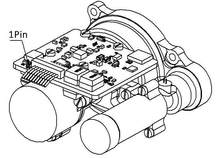
Connector connection 1Pin position
Software
Data
Data
The data transmission between the rangefinder and the upper computer includes the following contents:
● Control command: including single, 1Hz ranging instruction, 5Hz ranging instruction, query instruction, etc;
● Return data: including distance information, ambient temperature, rangefinder status, etc.
The data exchange between the rangefinder and the upper computer adopts RS422/TTL (two-choice 1), and its characteristics are as follows:
● Baud rate: 38400 (factory)/9600/57600/115200;
● Byte structure: low order in front, high order in back;
● Byte composition: 1-bit start bit, 8-bit data bit, no check, 1-bit stop bit.
Information
The format of the control command information is shown in the following table.
Control command information received by the rangefinder
| Byte | Illustrate | Byte data (command words, data, check bits) | Notes |
| 1 | Frame Header | 0x55 |
|
| 2-5 |
|
1 ranging: 0xF2 0x00 0x00 0xF2 | The feedback data is shown in the table below |
| 1Hz ranging:0xF3 0x01 0x00 0xF2 | |||
| 5Hz ranging:0xF3 0x02 0x00 0xF1 | |||
| Stop ranging:0xF3 0x00 0x00 0xF3 | |||
| Baud rate setting: 0xF6 _ _0xXX | ____ Set the baud rate/100 (hexadecimal representation), where 0xXX is an XOR of 2-4 bytes | ||
| Self check command: 0xF0 0x00 0x00 0xF0 | The feedback data is shown in the table below | ||
| Query instruction: 0xF8 0x00 0x00 0xF8 | |||
| Gating value setting: 0xF4 ___ ___ 0xXX | ___is the set strobe value (hexadecimal representation), and 0xXX is the exclusive OR of 2 to 4 bytes. | ||
| 6 | End of Frame | 0xAA |
|
The return data of the rangefinder is divided into regular data and self-test data.
● Regular data: including the number of targets, measurement distance, rangefinder status, etc. see the table below.
● Query data: including ambient temperature, rangefinder status, etc. See the table below.
● Regular data: including the number of targets, measurement distance, rangefinder status, etc. see the table below.
● Query data: including ambient temperature, rangefinder status, etc. See the table below.
Conventional data returned by distance measuring machines
| Byte | Illustrate | Byte value (hexadecimal) |
| 1 | Header | 0xAA |
| 2 | Number of targets |
|
| 3 | High Byte of First Target Distance Information |
|
| 4 | Low Byte of First Target Distance Information |
|
| 5 | First Target Distance Information Decimal Digits | Two decimal places after the decimal point |
| 6 | High Byte of End Target Distance Information |
|
| 7 | Low Byte of End Target Distance Information |
|
| 8 | Last Target Distance Information Decimal Digits | Two decimal places after the decimal point |
| 9 | Ranging status byte | Status word, see table below |
| 10~13 | Number of light output |
|
| 14 | Check word | Bytes 2-13 XOR |
| 15 | End of Frame | 0x55 |
Meaning of Status Word
| Serial Number | Byte 9 | Significance |
| 1 | 0xF2 | 1 Ranging |
| 2 | 0xF3 | 1Hz Ranging |
| 3 | 0xF4 | 5Hz Ranging |
| 4 | 0xF5 | Stop Ranging |
Query data sent back by rangefinder
| Byte | Illustrate | Byte Value (Hexadecimal) |
| 1 | Frame header | 0xCC |
| 2 | Standby | Standby |
| 3 | Ambient Temperature Byte | 8-bit signed number, unit: ℃ |
| 4 | Self Test Information Byte |
0x 00 indicates the query default value 0x 03 indicates that the self-check light is normal 0xFF indicates abnormal self-detected light |
| 5 | High Intensity Working Status Byte |
1: Normal operation mode flag bit 0: High-intensity working mode flag bit |
| 6 | Distance strobe value high byte | Hexadecimal representation |
| 7 | Low Byte of Distance Gating Value | |
| 8 | Baud rate high byte | Hexadecimal representation, baud rate is loopback data * 100 |
| 9 | Baud rate low byte | |
| 10 | Number of light is 8 bits high | Hexadecimal representation |
| 11 | ||
| 12 | Number of light out low 8 bits | |
| 13 | ||
| 14 | Check word | Bytes 2-13 XOR |
| 15 | End of Frame | 0x55 |
Baud Rate Settings
Baud rate setting operation method:
A.send "0x 55 0xF6 0x 00 0x 60 0x 96 0xXX" command to the laser range finder, I .e. set the baud rate to 9600bps; The rangefinder returns "CC 01 19 00 01 00 00 00 60 00 00 00 79 55", "0x 00 0x 60" indicates that the current baud rate has been set to 9600bps;
B.Send "0x 55 0xF6 0x 01 0x 80 0x 77 0xXX" command to the laser rangefinder, I .e. set the baud rate to 38400bps; The rangefinder returns "CC 01 19 00 01 00 00 01 80 00 00 00 00 98 55", and "0x 01 0x 80" indicates that the current baud rate has been set to 38400bps;
C.Send "0x 55 0xF6 0x 02 0x 40 0xB4 0xXX" command to the laser rangefinder, that is, set the baud rate to 57600bps; The rangefinder sends back "CC 01 19 00 01 00 00 02 40 00 00 00 00 5B 55", and "0x 02 0x 40" indicates that the current baud rate has been set to 57600bps;
D.send "0x 55 0xF6 0x 04 0x 80 0x 72 0xXX" command to the laser rangefinder, I .e. set the baud rate to 115200bps; The rangefinder returns "CC 01 19 00 01 00 04 80 00 00 00 9D 55", "0x 04 0x 80" indicates that the current baud rate has been set to 115200bps.
Hot Tags: 9km Range Finder Module, Manufacturers, Suppliers, Factory, China, Made in China, Customized, High Quality
Related Category
905nm Laser Range Finder Module
1535nm Laser Range Finder Module
1570nm Laser Range Finder Module
1.54um Laser Rangefinder Module
1064nm Laser Target Designator
Anti drone ststem module
Ranging Lidar Module
Send Inquiry
Please feel free to give your inquiry in the form below. We will reply you in 24 hours.