Home
>
Products > Laser Rangefinder Module > Anti drone ststem module > 2mrad 2km Laser Rangefinder module for Anti drone ststem


2mrad 2km Laser Rangefinder module for Anti drone ststem
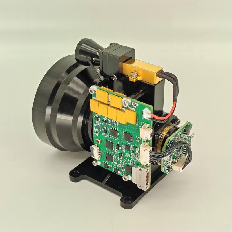
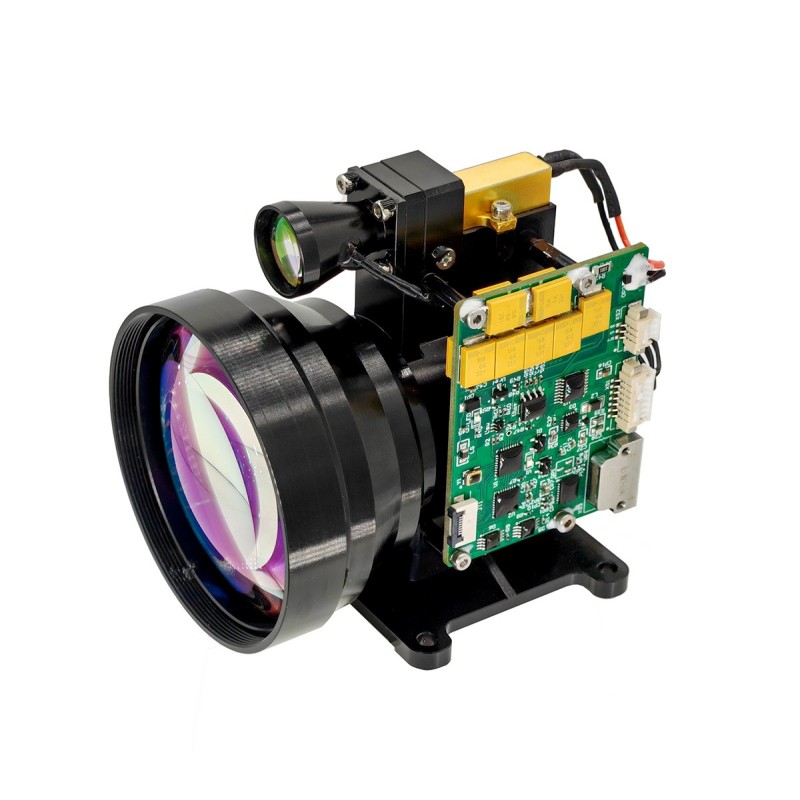
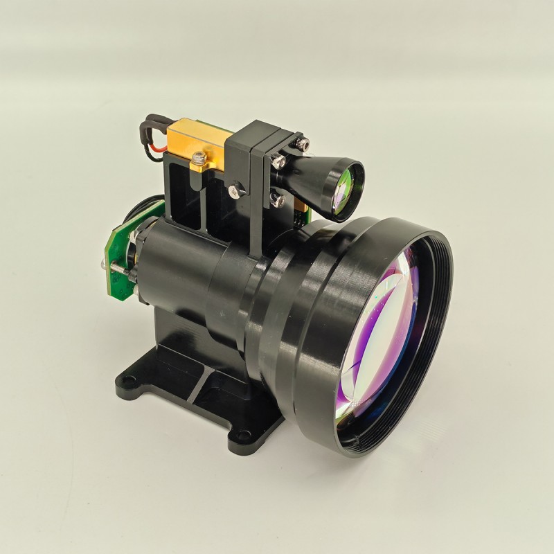
The compact STA-WR2000X Laser rangefinder module is highly suitable for integration into the air defense systems of the army and navy. The distance measurement module adopts the most advanced diode pumped erbium glass laser, which has high availability and low maintenance cost. Its 2mrad divergence angle can measure UAVs with a cross-section of 0.1 ㎡ up to 2000 meters, making it an important component of anti drone systems.
Send Inquiry
Product Description
1)Single ranging and continuous ranging;
2) Responding to laser ranging commands and stopping ranging at any time according to the stop command;
3) Outputs distance data and status information once per pulse during ranging;
4) It can report the cumulative number of transmitted laser pulses (no loss of power down);
5) Distance selection, before and after target indication;
6) Self-test function.
| Optical index | |
| Wavelength | 1535nm±5nm |
| Laser divergence Angle | ≤2mrad |
| Effective receiving aperture | 56mm |
| Range frequency | Single, 1~10Hz adjustable |
| Range | Visibility ≥ 12km, target reflectivity ≥ 0.3, humidity ≤ 80%, UAV ranging distance (0.25m × 0.25m) ≥ 2km |
| Ranging accuracy | ≤±1m(RMS) |
| Accuracy measurement | ≥98% |
| False alarm rate | ≤1% |
| Minimum measurement range | ≤50m |
| Laser axis stability | ≤0.05mrad |
| The optical axis is parallel to the installation reference | ≤0.3mrad |
| Mechanical indicators | |
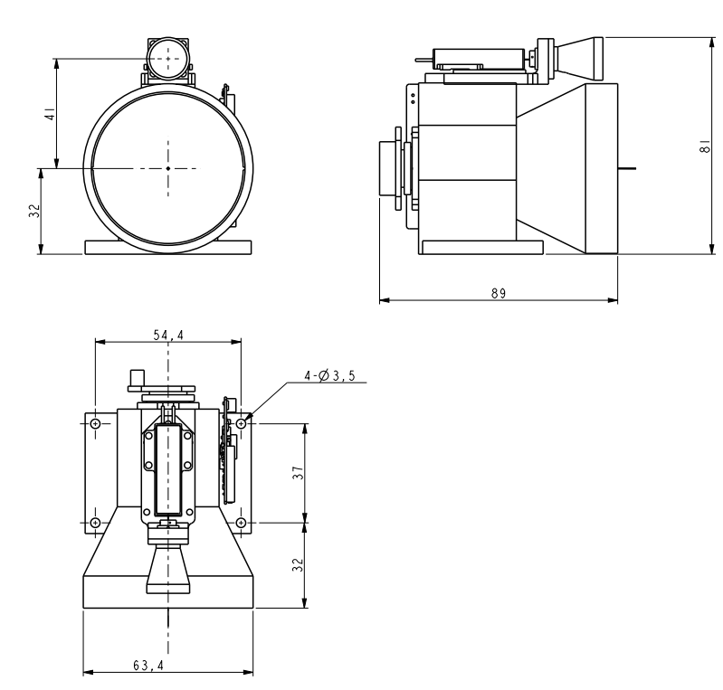
| Size | ≤90×63×82mm |
| Weight | ≤300g |
| Electrical indicators | |
| Supply electricity | DC9V~32V |
| Power dissipation | Work less than 3W@10Hz, peak power consumption less than 5W |
| Interface | RS422 interface, 115200bps |
| Power on control interface | When the safe distance is reached, power on and use it; or in low power mode to control its working state |
| Protection of circuit board | After the design and debugging of the circuit board is completed, it is required to coat the anti-shock paint and do the "three protection" treatment |
| Environmental suitability | |
| Working temperature | -40℃-65℃ |
| Storage temperature | -55℃-70℃ |
| Vibrate | GJB150.16 A-2009 "Military Equipment Laboratory Environmental Test Methods-Vibration Test" |
| Lash | GJB150.18 A-2009 "Military Equipment Laboratory Environmental Test Method-Impact Test" |
Note:
1.Ranging range description: the range will change under different test conditions and test targets, if you detect special targets, please contact the sales side to confirm;
2.Minimum range: 30m-100m fluctuations, it is recommended to 50m after normal use; due to the laser energy is large, close range use may burn the detector chip, so in the debugging, please bring a good mirror cover to prevent the detector chip is burned.
Mechanical structure diagram
External Interface
| Pin | Definition | Function | Notes |
| 1 | RX+ | RS422 Receiver + | Blue |
| 2 | RX- | RS422 Receiver - | Green |
| 3 | TX- | RS422 Transmission - | Purple |
| 4 | TX+ | RS422 Transmission + | Yellow |
| 5 | GND | Communication ground wire | White |
| 6 | VEE | Power supply + | Red |
| 7 | GND | Power supply - | Black |
| 8 | PWR EN | / | Ash |
OEM/ODM 1-15km Laser Ranging Module for Counter Unmanned Aerial Systems (C-UAS)
Communicating protocol
1. Transmission protocol: asynchronous serial communication;
2. Port rate: 115200;
3. Data bits: 10bits: one start bit, 8 data bits, one stop bit, invalid verification;
4. Data structure: The data consists of the header byte, command part, data length, parameter part and check byte;
5. Communication mode: the master control sends control commands to the ranging machine, and the ranging machine receives and executes the instructions. In the ranging state, the ranging machine sends data and status of the ranging machine back to the upper computer according to the ranging cycle. The communication format and command content are shown in the following table.
A) Main control sends
The format of the message to be sent is as follows:
| STX0 | CMD | LEN | DATA1H | DATA1L | CHK |
Table 2 Format description of the message sent
| order number | name | explain | code | remarks |
| 1 | STX0 | Message start flag | A5(H) |
|
| 2 | CMD | CW | See table 3 |
|
| 3 | LEN | DL | The number of all bytes except the start mark, command word, and checksum |
|
| 4 | DATAH | parameter | See table 3 |
|
| 5 | DATAL |
|
||
| 6 | CHK | XOR verification | Except for the valid byte, all other bytes are XORed |
|
The command is described as follows:
Table 3 Description of commands and data words sent by the master to the ranging machine
Table 3 Description of commands and data words sent by the master to the ranging machine
| order number | CW | function | data byte | remarks | length | Example code |
| 1 | 0x00 | cease | DATAH=00(H)DATAL=00(H) | The rangefinder stops measuring | Six bytes | A5 00 02 00 00 A7 |
| 2 | 0x01 | Single ranging | DATAH=00(H)DATAL=00(H) |
|
Six bytes | A5 01 02 00 00 A6 |
| 3 | 0x02 | Continuous ranging | DATAH=XX(H)DATAL=YY(H) | DATA describes the ranging period, in ms | Six bytes | A5 02 02 03 E8 4E (1Hz ranging) |
| 4 | 0x03 | self-checking | DATAH=00(H)DATAL=00(H) |
|
Six bytes | A5 03 02 00 00 A4 |
| 5 | 0x04 | Set the closest distance to the selection | DATAH=XX(H)DATAL=YY(H) | DATA describes the blind zone value, unit 1m | Six bytes | A5 04 02 00 64 C7(100m is the closest distance) |
| 6 | 0x06 | Cumulative number of light output queries | DATAH=00(H)DATAL=00(H) | Cumulative number of light output queries | Six bytes | A5 06 02 00 00 A1 |
| 7 | 0x11 | APD power is on | DATAH=00(H)DATAL=00(H) |
|
Six bytes | A5 11 02 00 00 B6 |
| 8 | 0x12 | APD power is off | DATAH=00(H)DATAL=00(H) |
|
Six bytes | A5 12 02 00 00 B5 |
| 9 | 0xEB | Number query | DATAH=00(H)DATAL=00(H) | Number query | Six bytes | A5 EB 02 00 00 4C |
a)Main control receives format
The format of the received message is as follows:
The format of the received message is as follows:
| STX0 | CMD | LEN | DATAn | DATA0 | CHK |
Table 4 Format description of received messages
| order number | name | explain | code | remarks |
| 1 | STX0 | Message start flag 1 | A5 (H) |
|
| 2 | CMD_JG | Data command word | See table 5 |
|
| 3 | LEN | DL | The number of all bytes except the start mark, command word, and checksum |
|
| 4 | Dn | parameter | See table 5 |
|
| 5 | D0 |
|
||
| 6 | CHK | XOR verification | Except for the valid byte, all other bytes are XORed |
|
Main control receiving status description:
Table 5 describes the data word sent by the rangefinder to the master controller
Table 5 describes the data word sent by the rangefinder to the master controller
| order number | CW | function | data byte | remarks | Overall length |
| 1 | 0x00 | cease | D1=00(H)D0=00(H) |
|
Six bytes |
| 2 | 0x03 | self-checking | D8 ~D1 | D8-D7: -5V voltage, unit 0.01V.D6-D5: Blind spot value, unit 1mD4: APD high voltage value, unit V;D3: char type, indicating APD temperature, unit: degrees Celsius;D2-D1: +5V voltage, unit 0.01V | 12 bytes |
| 3 | 0x04 | Distance to the nearest access setting, unit m | D1 D0 | DATA describes the nearest distance value, unit 1m;Start high and end low | Six bytes |
| 4 | 0x06 | Cumulative number of light output queries | D3~D0 | DATA expresses the number of lights, 4 bytes, with the high byte first | Seven bytes |
| 5 | 0x11 | APD power is on | D1=00(H)D0=00(H) | APD power is on | Six bytes |
| 6 | 0x12 | APD power off | D1=00(H)D0=00(H) | APD power is off | Six bytes |
| 7 | 0xED | Working overtime | 0x00 0x00 | The laser is under laser working protection and cannot be measured. | Six bytes |
| 8 | 0xEE | Effectiveness errors | 0x00 0x00 |
|
Six bytes |
| 9 | 0XEF | Serial port communication timeout | 0x00 0x00 |
|
Six bytes |
| 10 | 0x01 | Single range measurement (single target, zero for the second and third targets, zero for the third target at the beginning and end of the target) | D9D8 D7 D6D5 D4 D3D2 D1 D0 | D8-D6 first target distance (unit 0.1m)D5-D3 distance to the second target (unit: 0.1m)D2-D0 third target distance (unit 0.1m)3. Goals are from near to farD9 (bit7-bit0) flag byte:D9 is the 7th position indicating the main wave; 1: there is a main wave, 0: no main wave.D9 is the 6th position indicating echo; 1: there is echo, 0: no echoD9 The fifth position indicates the laser status; 1: normal laser, 0: laser faultD9 is the fourth bit of the timeout flag, 1: normal, 0: timeoutD9 is invalid at the 3rd position (set to 1);D9 The second position indicates the APD status; 1: normal, 0: errorD9 is the first position to indicate whether there is a previous target; 1: there is a previous target, 0: no previous target (target in the blind area).D9 The 0th bit indicates whether there is a subsequent target; 1: there is a subsequent target, 0: no subsequent target (the target after the main target is the subsequent target) | 14 bytes |
| 11 | 0x02 | Continuous ranging (single target, zero for the second and third targets, zero for the third target at the beginning and end of the target) | D9 D8 D7 D6D5 D4 D3D2 D1 D0 | D8-D6 first target distance (unit 0.1m)D5-D3 distance to the second target (unit: 0.1m)D2-D0 third target distance (unit 0.1m)3. Goals are from near to farD9 (bit7-bit0) flag byte:D9 is the 7th bit to indicate the main wave; 1: there is a main wave, 0: no main wave.D9 is the 6th position indicating echo; 1: there is echo, 0: no echoD9 The fifth position indicates the laser status; 1: normal laser, 0: laser faultD9 is the fourth bit of the timeout flag, 1: normal, 0: timeoutD9 is invalid at the 3rd position (set to 1);D9 The second position indicates the APD state; 1: normal, 0: errorD9 is the first position to indicate whether there is a previous target; 1: there is a previous target, 0: no previous target (target in the blind area).D9 The 0th bit indicates whether there is a subsequent target; 1: there is a subsequent target, 0: no subsequent target (the target after the main target is the subsequent target) | 14 bytes |
| 12 | 0xEB | Number query | D17…… D0 | D17 D16 D15 D14 D13 D12 Whole machine model codeD11D10 Product numberD9 D6 software versionD5 D4 APD numberD3 D2 Laser numberVersion D1 of FPGA | 22 bytes |
| Note: ① Undefined data byte/bit, default is 0; | |||||
Hot Tags: 2mrad 2km Laser Rangefinder module for Anti drone ststem, Manufacturers, Suppliers, Factory, China, Made in China, Customized, High Quality
Related Category
905nm Laser Range Finder Module
1535nm Laser Range Finder Module
1570nm Laser Range Finder Module
1.54um Laser Rangefinder Module
1064nm Laser Target Designator
Anti drone ststem module
Ranging Lidar Module
Send Inquiry
Please feel free to give your inquiry in the form below. We will reply you in 24 hours.