Home
>
Products > Laser Rangefinder Module > 905nm Laser Range Finder Module > 1200m Mini Laser Rangefinder Module(LRF)


")
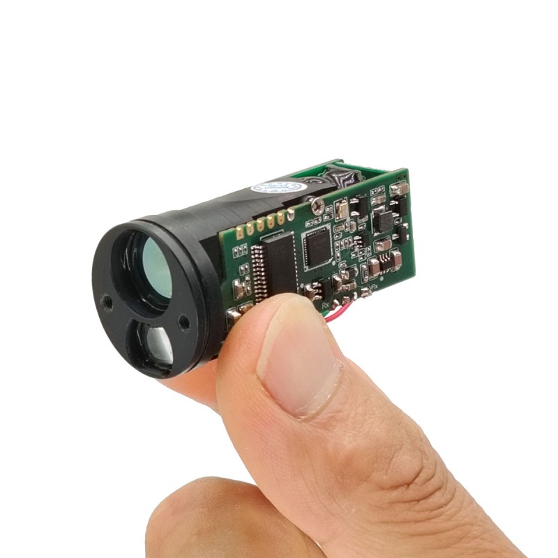
1200m Mini Laser Rangefinder Module(LRF)
STA-M series miniature laser rangefinder module adopts 905nm semiconductor laser components, with low power consumption, small size, stable performance and other characteristics, suitable for thermal imaging, night vision and other handheld mobile devices and miniaturized UAV pod equipment integration.
Measurement range: 5-1200meters
Measurement of trees ≥1000 meters
Measurement accuracy ±1m
Weight ≤14 ±0.5g
Send Inquiry
Product Description
Technical parameters are shown in the following table
| Model | STA-M010X | |
| Laser wavelength | 905nm | |
| Ranging capability | Building | 1200m |
| Trees | 1000m | |
| Laser grade | Class 1 Eye safety | |
| Mini range | 5m | |
| Resolution | ±0.1m | |
| Operating Current | ≤90mA | |
| Standby current | ≤20mA | |
| Power consumption | Standby≤0.09W | |
| Peak≤0.23W | ||
| Communication Interface | TTL | |
| Operating Temperature | ·-20℃~+55℃ | |
| Storage Temperature | ·-30℃~+60℃ | |
| Input Voltage | 3-5V(Recommended 5V power supply) | |
| Beam divergence angle | 5 mard | |
| Ranging Frequency | 1-3Hz | |
| Power | ≤1 mW Safe for human eyes | |
| Ranging method | Pulse | |
| Weight | 14±0.5g | |
| Size | Φ23x47mm | |
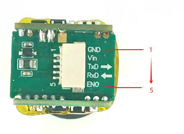
Interfaces and pins are defined as shown in the following table
| TTL interface | |||
| Pin | Pin Definition | Describe | Schematic drawing |
| 1 | GND | Power supply - |
|
| 2 | Vin | Power supply + | |
| 3 | TXD | Transmit Data | |
| 4 | RXD | Received Data | |
| 5 | ENO | Enable Pin, Reserved | |
|
|
|
|
|
Module Communication Command Chart
| Master Command | ||
| Command code | Description | Broadcast add. response |
| 0x80 | Read rangefinder status | NO |
| 0x81 | Read measuring result | NO |
| 0x83 | Start ranging | NO |
| 0x84 | Stop ranging | NO |
| 0x9E | Communication parameter program | YES |
| 0xBE | Read communication parameter | YES |
| 0xC0 | Communication test | YES |
| 0xC1 | Read Firmware Version | YES |
|
|
|
|
| Slave Response | ||
| Recognition code | Description | |
| 0x60 | Simple reponse Frame | |
| 0x01 | Range data frame | |
| 0x20 | rangefinder status frame | |
| 0x21 | Communication parameter frame | |
| 0xE0 | Error message frame | |
NOTE
1. The Communication Frame Format:
SlaveID + instruction + parameter +checksum
2. The interval between two adjacent frames has to be at least the time of 1.5 byte when
sent out, when it is less than 1ms, it is regarded as 1ms;
600BPS: 25ms
1200BPS: 12.5ms
2400BPS: 6.25ms
4800BPS: 3.125ms
9600BPS: 1.56ms
19200BPS: 1ms(0.78ms < 1ms, take 1ms)
3. Sending calculate of checksum;
This module uses the verification mode of byte by byte accumulation sum, SlaveID is not
included in the verification, sending checksum at last.
Such as calculate check sum of scanning mode instruction"0x83 0x40":
A.Calculate accumulation sum:0x83 + 0x40 = 0xC3;
B.Take LSB[D7..D0]:0xC3;
C.Calculate 2's complement:0x100 - 0xC3 = 0x3D, 0x3D is checksum;
Add slave address when mater sends: 0x10 0x83 0x40 0x3D
4. Verification receipt;
Such as receive communication frame: 0x10 0x83 0x40 0x3D, verification not including
slave address 0x10
A.Calculate accumulation sum:0x83 + 0x40 + 0x3D = 0x100;
B.Take LSB of accumulation sum: 0x00; 0x00 is verification result;
If verification result is 0x00, that means received data is right; If verification result
is not 0x00, that means received data is wrong.
Module Command Description
Note:In the example, the slave address of each command is 0x10;in application, the slave address will be the programmed one.
1、Communication test(0xC0);
| Master sends | ||
| Command code | Parameter | Description |
| 0xC0 | None |
|
| Slave responses | ||
| Recognition code | Parameter | Description |
| 0x60 | None |
|
| Example | ||
|
Master sends:0x10 0xC0 0x40;0x40 is checksum Slave response:0x10 0x60 0xA0;0xA0 is checksume |
||
2、Command slave to start ranging (0x83);
| Master sends | ||
| Command code | Parameter | Description |
| 0x83 | byte1 | D7: Reserve |
| D6: Continuous ranging mode, 0 = off; 1 = on; | ||
| D5: Fog mode, 0 = off; 1 = on; | ||
| D4: Data unit, 0 = meter; 1 = yard; | ||
| D3 - D0: Working Mode, 0 = ranging; 1 = speed; 2 = Small Target Mode; | ||
| Slave responses | ||
| Recognition code | Parameter | Description |
| 0x60 | None | If slave is set as automatic export mode, slave responds 0x60 first after reception of start ranging command, after ranging is finished, it will then send out ranging result; |
| Example | ||
|
Master sends: 0x10 0x83 0x00 0x7D:Mode 0 is for single measure, data unit is meter; 0x10 0x83 0x40 0x3D:Mode 0 is for continuous mesure, data unit is meter; 0x10 0x83 0x10 0x6D:Mode 0 is for single measure, data unit is yard; 0x10 0x83 0x20 0x2D:Mode 0 is for continuous mesure, data unit is yard; Slave response: 0x10 0x60 0xA0; |
||
Note: 1、If module data export method is set as query mode, then it can only do single measure;
2.In speed mode, continuous ranging function is null, that is no continuous speed measure;
3.Fog mode is only valid for device with fog mode function;
4.Slave will send 0x60 response frame after reception of start ranging command, it will start to send ranging result after ranging is finished.
3、command slave stop ranging(0x84);
| Master sends | ||
| Command code | Parameter | Description |
| 0x84 | None |
|
Note: After master sends command to slave to do continuous ranging, it needs to send this command to slave to stop ranging. If master sends command to slave to do single time ranging, then no need to send this command, cause slave will stop ranging automatically after ranging is finished.
4、reading slave status(0x80);
| Master sends | ||
| Command code | Parameter | Description |
| 0x80 | None |
|
| Slave responses | ||
| Recognition code | Parameter | Description |
| 0x20 | byte1 |
D7:1 = Rangefinder Busy; 0 = Ranging finished; D6: 1=Rangefinder Malfunction; 0=No malfunction; D5-D2: Reserve; D1: 0=Angle sensor prohibited; 1=Angle senser enabled; D0: 0=Angle sensor is normal; 1=Abnormal Angle sensor; |
| byte2 | Reserve | |
5、read range finder result(0x81);
| Master sends | |
| Description |
|
|
|
|
| Slave responses | |
| Description |
|
|
D7::Distance data, 0=data valid; 1=Invalid data; D6::Angle data, 0=data valid; 1=Invalid data; D5:Data resolution, 0 = 0.5/LSB;1 = 0.1/LSB; D4:Data unit, 0 = meter; 1 = yard; D3 - D0:Working Mode, 0 = Ranging; 1 = Speed; |
|
|
When distance is valid:Distance[D15..D8]; When distance is invalid:0x80 = Ranging no result; 0x81= System error; |
|
|
When angle is valid: Distance[D7..D0]; When angle is invalid: Reserve; |
|
|
|
|
| Example | |
|
1、slave sends distance frame: 0x10 0x01 0x60 0x12 0xD7 0xB6 distance value = 0x12D7 = 4823 = 482.3m 2、slave sends speed frame:0x10 0x01 0x21 0x03 0xD7 0x04 speed value = 0x03D7 = 983 = 98.3km/h 3、slave sends distance frame:0x10 0x01 0xE0 0x80 0x00 0x9F The distance value is invalid (the first byte is 0xE0, D7=1) |
|
6、write slave communication baud rate(0x9E), The factory setting is 19200BPS;
| Master sends | ||
| Command code | Parameter | Description |
| 0x9E | byte1 | has to be 0x90 |
| byte2 | Reserve | |
| byte3 | Reserve | |
| byte4 |
baud rate setting: 0 = 1200BPS; 1 = 2400BPS; 2 = 4800BPS; 3 = 9600BPS; 4 = 19200BPS(Default); |
|
| Slave responses | ||
| Recognition code | Parameter | Description |
| (please refer to the slave respons part of reading slave parameter) | ||
| Example | ||
| If master sends frame: 0x10 0x9E 0x90 0x00 0x00 0x04 0xCE; It's means: Set baud rate of slave as 19200BPS, | ||
Note:New baud rate is only valid after module is restarted;
7、write slave address(0x9E), Factory settings: 0x10;
| Master sends | ||
| Command code | Parameter | Description |
| 0x9E | byte1 | Must be 0x91 |
| byte2 | Reserve | |
| byte3 | Reserve | |
| byte4 | slave new address; | |
| Slave responses | ||
| Recognition code | Parameter | Description |
| (please refer to the slave respons part of reading slave parameter) | ||
| Example | ||
| To write slave address as 0x20, then master sends: 0x10 0x9E 0x91 0x00 0x00 0x20 0xB1 | ||
Note: 1. New slave address is valid after the device is restarted
2. 0x00 is broadcast address, so slave address can't be set as 0x00;
3. Default slave address is 0x10;
8、write measured result export method(0x9E);
| Master sends | ||
| Command code | Parameter | Description |
| 0x9E | byte1 | Must be 0x92 |
| byte2 | Reserve | |
| byte3 | Reserve | |
| byte4 |
Measured result export method selecttiong: 0 = Query mode(slave can only export data when master sends reading command) 1(Default) = Automatic mode (After ranging finished, it sends out data automatically); |
|
| Slave responses | ||
| Recognition code | Parameter | Description |
| (Please refer to the slave respons part of reading slave parameter) | ||
| Example | ||
| To change data export to automatic exporting, then master sends:0x10 0x9E 0x92 0x00 0x00 0x01 0xCF | ||
9、Set UART IO voltage (0x9E), Factory setting: 3.3V;
| Example | ||
| Command code | Parameter | Description |
| 0x9E | byte1 | Must be 0x93 |
| byte2 | Reserve | |
| byte3 | Reserve | |
| byte4 | UART IO voltage Setting: 72 - 199, 0.025V/LSB; | |
| Slave responses | ||
| Recognition code | Parameter | Description |
| (please refer to the slave respons part of reading slave parameter) | ||
| Example | ||
| Change UART IO voltage to 3.3V, then master sends:0x10 0x9E 0x93 0x00 0x00 0x84 0x4B | ||
Note:VIO = Setting * 0.025V, Default VIO = 3.3V
10、Reading communication parameter (0xBE);
| Master sends | ||
| Command code | Parameter | Description |
| 0xBE | byte1 | Must be 0x91 or 0x92 |
| Slave responses | ||
| Recognition code | Parameter | Description |
| 0x21 | byte1 | Slave address: 0x01 - 0xFF |
| byte2 |
D4: Data export method ; D3 - D0:Baud Rate setting; |
|
| byte3 | UART IO voltage setting | |
11、Slave sends wrong information(0xE0);
| Slave responses | ||
| Recognition code | Parameter |
|
| 0xE0 | byte1 |
D7 - D3: Reserve; D2:1 = Communication parameter error; D1:1 = Unrecognizable commmand; D0:1 = Checksum error; |
12、Read Firmware Version(This command was supported only in V7.00 or newer version;) ;
| Master Sends | ||
| Command Code | Parameter |
|
| 0xC1 | None |
|
| Slave responses | ||
| Recognition code | Parameter | Notes |
| 0x61 | byte0 | Majo Version(BCD) |
| byte1 | Minor Version(BCD) | |
| Example | ||
|
Slave responses: 0x10 0x61 0x07 0x00 0x98 Data "0x07 0x00" means firmware version is V7.00. |
||
Hot Tags: 1200m Mini Laser Rangefinder Module(LRF), Manufacturers, Suppliers, Factory, China, Made in China, Customized, High Quality
Related Category
905nm Laser Range Finder Module
1535nm Laser Range Finder Module
1570nm Laser Range Finder Module
1.54um Laser Rangefinder Module
1064nm Laser Target Designator
Anti drone ststem module
Ranging Lidar Module
Send Inquiry
Please feel free to give your inquiry in the form below. We will reply you in 24 hours.


")