Home
>
Products > Laser Rangefinder Module > 1535nm Laser Range Finder Module > 1535nm 3km Miniature Laser Ranging module


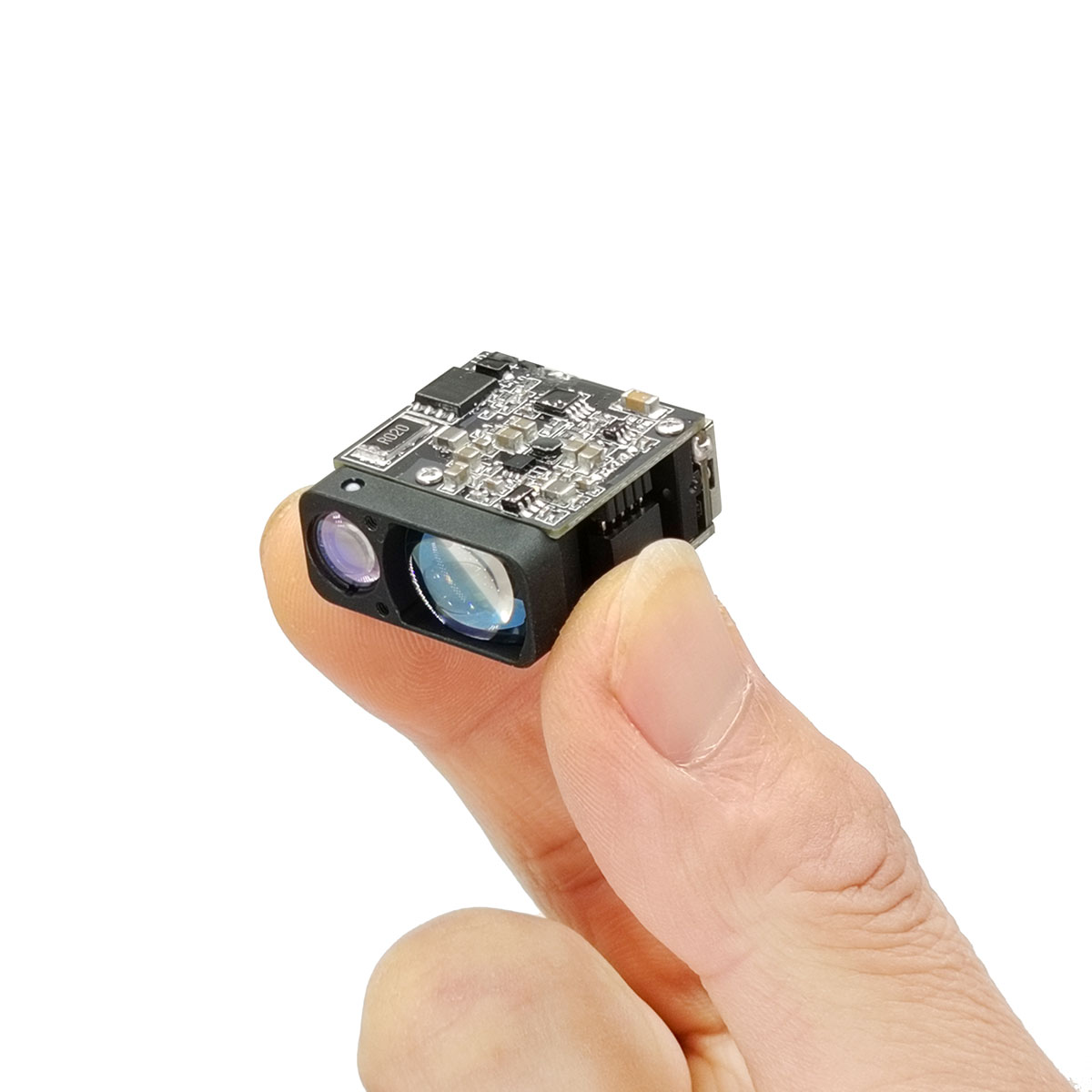
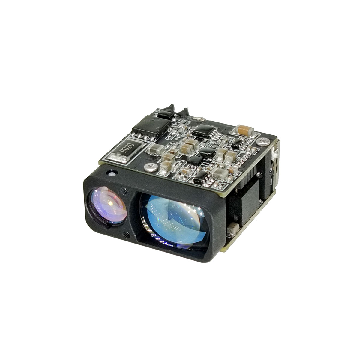
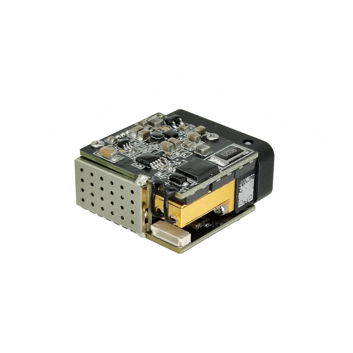
1535nm 3km Miniature Laser Ranging module
The STA-AM30X laser ranging module utilizes Time-of-Flight (TOF) technology to achieve precise distance measurement from 10 meters to 4000 meters. It supports a ranging frequency of 1Hz to 10Hz and features a UART (TTL 3.3V) communication interface. Functions include single-shot ranging, continuous ranging, first/last target recognition, and multi-target ranging, making it suitable for high-precision distance measurement applications.
Send Inquiry
Product Description
TECHNICAL SPECIFICATIONS
| Project | Performance Indicators | |
| Model | STA-AM30X | |
| Performance Indicators | Laser Wavelength | 1535±5nm |
| Eye- safety | Class Ⅰ (IEC 60825-1) | |
| Divergence Angle | ≤0.6 mrad | |
| Laser Energy | ≥100 μJ | |
| Field of View (FOV) | ~ 7. 4mrad | |
| Maximum Measuring Range(Visibility > 8km) | ≥ 4000m @60% Reflectivity, Building Target | |
| ≥3000m @30% Reflectivity, 2.3×2.3m Target | ||
| ≥1500m @30% Reflectivity, 0.5×1.7m Target | ||
| ≥800m @30% Reflectivity, 0.2×0.3m Target | ||
| Minimum Range | ≤10 m | |
| Ranging Frequency | 1Hz ~10Hz | |
| Multi-Target Detection | Up to 3 targets | |
| Ranging Accuracy | ±1 m | |
| Accuracy Rate | ≥98% | |
| False Alarm Rate | ≤1% | |
| Electrical Specifications | Interface Type | UART(TTL 3.3V) |
| Power Supply Voltage | DC 3~5V | |
| Standby Power Consumption(Full Temperature Range) | ≤10mW (Power on pulled low) | |
| ≤0.8W (Power on pulled high) | ||
| Operating Power Consumption(Full Temperature Range) | 5V.≤0.9W@1Hz | |
| 5V, <1. 5W@10Hz | ||
| Peak Power Consumption | <3W@5V | |
| Start-up Time | ≤350ms (After startup, response time ≤20ms) | |
| Physical Characteristics | Weight | ≤ 141g |
| Dimensions | ≤ 27×25×15.5mm(L×W×H) | |
| Shock | 1200g, 1ms | |
| Vibration | 5~50~5 Hz, 1 octave/min, 2.5g | |
| Environmental Adaptability | Operating Temperature | -40 ~ +70℃ |
| Storage Temperature | -45 ~ +70℃ | |
| Reliability | MTBF>1500h | |
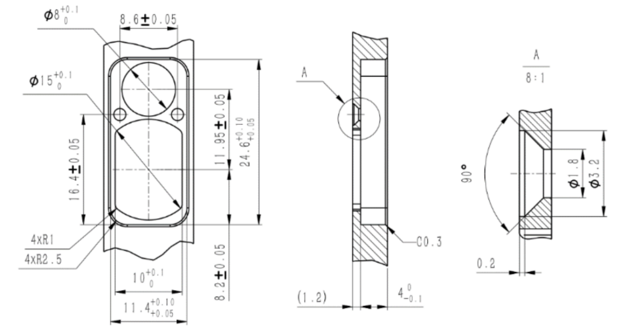
OUTLINE DIMENSION(mm)
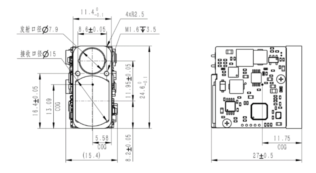
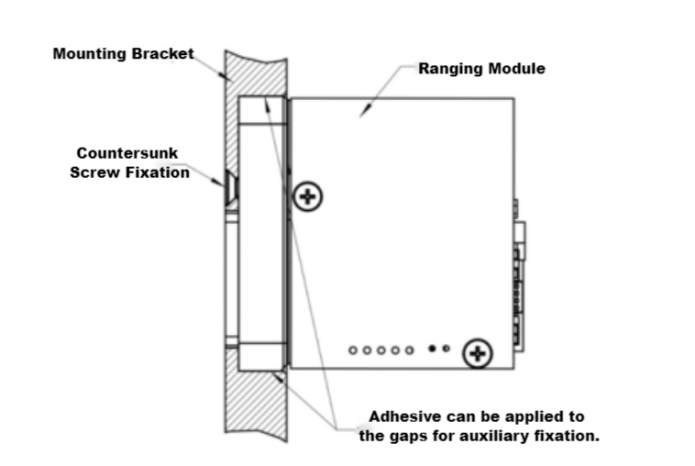
Recommended mounting bracket dimensions are as follows:
Installation Diagram:
PIN interface
Interface Type: UART (TTL 3.3V)
Connector Model: FWF08002-S06B13W5M (Tesga Connector)
| Pin | Definition | Description | |
| 1 | POWER_ON | Module Power Switch, TTL 3.3V Level;Module On (>2.7V), Module Off (<0.3V) | |
| 2 | UART_RX | Serial Port Receiver, TTL 3.3V Level | |
| 3 | UART_TX | Serial Port Transmitter, TTL 3.3V Level | |
| 4 | NC | ||
| 5 | Power Positive | Power Supply, 3~5V | |
| 6 | GND | Serial Port Ground |
Cable Definition:
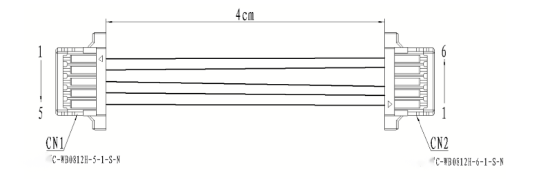
Matching Cable Pinout:
| CN1(C-WBO812H-5-1-S-N) | CN2(C-WBO812H-6-1-S-N) | Cable Specifications | Color |
| 1 | 6 | AWG32 | Black |
| 2 | 5 | AWG32 | Red |
| 3 | 3 | AWG32 | Yellow |
| 4 | 2 | AWG32 | Green |
| 5 | 1 | AWG32 | White |
Embedded software
1 Protocol description
1.1 Communication rate and format
| Format standard | Baud Rate: 115200bps (Factory Default) / 57600bps / 38400bps / 9600bpsByte data format: 1 start bit, 8 data bits, 1 stop bit, no verification |
1.2 Basic packet format
| Section description | Section length(number of bytes) | Value range | Remarks |
| Frame header | 2 | 0xEE 0x16 | Fixed value |
| Data length | 1 | 2~7 | The data length is the total number of bytes in the three parts: device code, command code and command parameters |
| Equipment code | 1 | 0x03 | Fixed value, LRF S Series ranging module |
| Command code | 1 | 0~255 | Indicates the control object of the current control command |
| Command parameters | 0~4 | 0~255 | Indicates the control object parameters of the current control command |
| Checksum | 1 | 0~255 | Checksum is the sum of all byte data in the three parts of equipment code, command code and command parameters, with the lower 8 bits |
1.3 control command (system→ranging module)
| Command code | Explain | Command parameter bytes |
| 0x01 | Equipment self inspection | 0 |
| 0x02 | Single ranging | 0 |
| 0x03 | Set first / last / multiple targets | 1 |
| 0x04 | Continuous ranging | 0 |
| 0x05 | Stop ranging | 0 |
| 0xA0 | Set baud rate of laser ranging module | 4 |
| 0xA1 | Set continuous ranging frequency | 2 |
| 0xA2 | Set minimum gating distance | 2 |
| 0xA3 | Query minimum gating distance | 0 |
| 0xA4 | Maximum gating distance | 2 |
| 0xA5 | Query the maximum gating distance | 0 |
| 0xA6 | Query FPGA software version number | 0 |
| 0xA7 | Query MCU software version number | 0 |
| 0xA8 | Query hardware version number | 0 |
| 0xA9 | Query Sn number | 0 |
| 0x90 | Total times of light output | 0 |
| 0x91 | Query the power on and light out times this time | 0 |
1.4 Response data (ranging module → system)
| Command code | Explain | Command parameter bytes |
| 0x01 | Equipment self inspection | 4 |
| 0x02 | Single ranging | 7 |
| 0x03 | Set first / last / multiple targets | 0 |
| 0x04 | Continuous ranging | 4 |
| 0x05 | Stop ranging | 0 |
| 0x06 | Ranging abnormality (only when the state in the ranging abnormality command is abnormal, the command is returned after the response command of single ranging or continuous ranging is returned) | 4 |
| 0xA0 | Set baud rate of laser ranging module | 4 |
| 0xA1 | Set continuous ranging frequency | 2 |
| 0xA2 | Set minimum gating distance | 2 |
| 0xA3 | Query minimum gating distance | 2 |
| 0xA4 | Maximum gating distance | 2 |
| 0xA5 | Query the maximum gating distance | 2 |
| 0xA6 | Query FPGA software version number | 4 |
| 0xA7 | Query MCU software version number | 4 |
| 0xA8 | Query hardware version number | 4 |
| 0xA9 | Query Sn number | 3 |
| 0x90 | Total times of light output | 3 |
| 0x91 | Query the power on and light out times this time | 3 |
1.5 Operation process
fter the ranging module is powered on, it is in the standby mode by default. It needs to enable the module power switch (power_on is pulled up) for about 0.5 s (the driving capacitor completes charging), and then all the command operations in 6.2 below can be carried out.
2 Specific agreement
2.1 Equipment self inspection
2.1.1 Send to laser ranging module:
| Byte | 0 | 1 | 2 | 3 | 4 | 5 |
| Describe | 0xEE | 0x16 | 0x02 | 0x03 | 0x01 | 0x04 |
2.1.2 Laser ranging module return:
| Byte | 0 | 1 | 2 | 3 | 4 | 5 | 6 | 7 | 8 | 9 |
| Describe | 0xEE | 0x16 | 0x06 | 0x03 | 0x01 | Status3 | Status2 | Status1 | Status0 | Check_sum |
| Status3: reservedStatus2: echo intensity 0x00~0xFFStatus1: bit0 -- FPGA system status; 1 Normal 0 Exceptionbit1 -- laser light output state; 1 light output 0 no lightbit2 -- main wave detection status; 1 main wave 0 no main wavebit3 -- echo detection status; 1 echo 0 no echobit4 -- bias switch status; 1 bias on 0 bias offbit5 -- bias output state; 1 the bias voltage is normal 0 bias abnormalbit6 -- temperature state; 1 the temperature is normal 0 temperature abnormal bit7 -- light output off state; 1 valid 0 invalidStatus0: bit0 -- 5v6 power status; 1 normal 0 exception | ||||||||||
2.2 Single ranging
2.2.1 Send to laser ranging module:
| Byte | 0 | 1 | 2 | 3 | 4 | 5 |
| Describe | 0xEE | 0x16 | 0x02 | 0x03 | 0x02 | 0x05 |
2.2.2 Laser ranging module return:
| Byte | 0 | 1 | 2 | 3 | 4 | 5 | 6 | 7 | 8 | 9 |
| Describe | 0xEE | 0x16 | 0x06 | 0x03 | 0x02 | Status | Ranging value integer high 8 bits | Ranging value integer lower 8 bits | Ranging value decimal places | Check_sum |
| When ranging the first / last target:Status: 0x00 indicates that the ranging result is a single target; 0x01 indicates that there is a front target in the ranging result; 0x02 indicates that there is a rear target in the ranging result; 0x03 reserved; 0x04 indicates that the ranging result is out of range; 0x05 reserved;In case of multi-target ranging:Status_ bit3~0: 0x0 indicates that the ranging result is a single target; 0x1 indicates that there is a front target in the ranging result; 0x2 indicates that there is a rear target in the ranging result; 0x3 indicates that the ranging result has front target and rear target; 0x4 indicates that the ranging result is out of range; 0x5 reserved;Status_ bit7~4: 0x0 ~ 0xf indicates the current distance result number; Value range [0, N-1], number of targets 1 ≤ N ≤ 16;Range value = range value integer high 8 bits × 256 + range value integer low 8 bits + range value decimal bits × 0.1, unit m | ||||||||||
2.3 Set first / last / multiple targets
2.3.1 Send to laser ranging module:
| Byte | 0 | 1 | 2 | 3 | 4 | 5 | 6 |
| Describe | 0xEE | 0x16 | 0x03(data length) | 0x03 | 0x03 | Target | Check_sum |
| Target:0x01 Set the first target ranging; 0x02 set terminal target ranging; 0x03 set multi-target ranging; | |||||||
2.3.2 Laser ranging module return:
| Byte | 0 | 1 | 2 | 3 | 4 | 5 |
| Describe | 0xEE | 0x16 | 0x02 | 0x03 | 0x03 | 0x06 |
2.4 Continuous ranging
2.4.1 Send to laser ranging module:
| Byte | 0 | 1 | 2 | 3 | 4 | 5 |
| Describe | 0xEE | 0x16 | 0x02 | 0x03 | 0x03 | 0x06 |
2.4.2 Laser ranging module return:
| Byte | 0 | 1 | 2 | 3 | 4 | 5 | 6 | 7 | 8 | 9 |
| Describe | 0xEE | 0x16 | 0x06 | 0x03 | 0x04 | Status | Ranging value integer high 8 bits | Ranging value integer lower 8 bits | Ranging value decimal places | Check_sum |
| When ranging the first and last targets:Status: 0x00 indicates that the ranging result is a single target; 0x01 indicates that there is a front target in the ranging result; 0x02 indicates that there is a rear target in the ranging result; 0x03 reserved; 0x04 indicates that the ranging result is out of range; 0x05 reserved;In case of multi-target ranging:Status_ bit3~0: 0x0 indicates that the ranging result is a single target; 0x1 indicates that there is a front target in the ranging result; 0x2 indicates that there is a rear target in the ranging result; 0x3 indicates that the ranging result has front target and rear target; 0x4 indicates that the ranging result is out of range; 0x5 reserved;Status_ bit7~4: 0x0 ~ 0xf indicates the current distance result number; Value range [0, N-1], number of targets 1 ≤ N ≤ 16; | ||||||||||
2.5 Stop ranging
2.5.1 Send to laser ranging module:
| Byte | 0 | 1 | 2 | 3 | 4 | 5 |
| Describe | 0xEE | 0x16 | 0x02 | 0x03 | 0x05 | 0x08 |
2.5.2 Laser ranging module return:
| Byte | 0 | 1 | 2 | 3 | 4 | 5 |
| Describe | 0xEE | 0x16 | 0x02 | 0x03 | 0x05 | 0x08 |
2.6 Ranging anomaly
Laser ranging module return:
| Byte | 0 | 1 | 2 | 3 | 4 | 5 | 6 | 7 | 8 | 9 | |
| Describe | 0xEE | 0x16 | 0x06 | 0x03 | 0x06 | reserve | reserve | reserve | Status1 | Check_sum | |
| Status1: bit0 -- FPGA system status; 1 normal 0 exception Bit1 -- laser light output state; 1 light output 0 no light Bit2 -- main wave detection status; 1 main wave 0 no main wave Bit3 -- echo detection status; 1 echo 0 no echo Bit4 -- bias switch status; 1 bias on 0 bias off Bit5 -- bias output state; 1 The bias voltage is normal 0 bias abnormal Bit6 -- temperature state; 1 The temperature is normal 0 abnormal temperature Bit7 -- light output off state; 1 valid 0 is invalidThis instruction is returned only when bit0~7 in status1 is abnormal. | |||||||||||
2.7 Set baud rate of laser ranging module
2.7.1 Send to laser ranging module:
| Byte | 0 | 1 | 2 | 3 | 4 | 5 | 6 | 7 | 8 | 9 |
| Describe | 0xEE | 0x16 | 0x06 | 0x03 | 0xA0 | BaudHigh24 | BaudHigh16 | BaudLow8 | BaudLow0 | Check_sum |
2.7.2 Laser ranging module return:
| Byte | 0 | 1 | 2 | 3 | 4 | 5 | 6 | 7 | 8 | 9 |
| Describe | 0xEE | 0x16 | 0x06 | 0x03 | 0xA0 | BaudHigh24 | BaudHigh16 | BaudLow8 | BaudLow0 | Check_sum |
2.8 Set continuous ranging frequency
2.8.1 Send to laser ranging module:
| Byte | 0 | 1 | 2 | 3 | 4 | 5 | 6 | 7 |
| Describe | 0xEE | 0x16 | 0x04(data length) | 0x03 | 0x0A1 | Freq | Num | Check_sum |
| Freq: 0x01~0x0A Single / continuous ranging frequencyNum:0x00 reserve | ||||||||
2.8.2 Laser ranging module return:
| Byte | 0 | 1 | 2 | 3 | 4 | 5 |
| Describe | 0xEE | 0x16 | 0x02 | 0x03 | 0xA1 | 0xA4 |
2.9 Set minimum gating distance
2.9.1 Send to laser ranging module:
| Byte | 0 | 1 | 2 | 3 | 4 | 5 | 6 | 7 |
| Describe | 0xEE | 0x16 | 0x04(data length) | 0x03 | 0xA2 | DIS_H | DIS_L | Check_sum |
| DIS_H: Distance high 8 bitsDIS_L: Distance lower 8 bitsDIS: 10~20000 Minimum gating distance range, in M | ||||||||
2.9.2 Laser ranging module return:
| Byte | 0 | 1 | 2 | 3 | 4 | 5 | 6 | 7 |
| Describe | 0xEE | 0x16 | 0x04(data length) | 0x03 | 0xA2 | DIS_H | DIS_L | Check_sum |
| DIS_H: Distance high 8 bitsDIS_L: Distance lower 8 bitsDIS: 10~20000 Minimum gating distance range, in M | ||||||||
2.10 Query minimum gating distance
2.10.1 Send to laser ranging module:
| Byte | 0 | 1 | 2 | 3 | 4 | 5 |
| Describe | 0xEE | 0x16 | 0x02 | 0x03 | 0xA3 | 0xA6 |
2.10.2 Laser ranging module return:
| Byte | 0 | 1 | 2 | 3 | 4 | 5 | 6 | 7 |
| Describe | 0xEE | 0x16 | 0x04(data length) | 0x03 | 0xA3 | DIS_H | DIS_L | Check_sum |
| DIS_H: Distance high 8 bitsDIS_L: Distance lower 8 bitsDIS: 10~20000 Minimum gating distance range, in M | ||||||||
2.11 Set maximum gating distance
2.11.1 Send to laser ranging module:
| Byte | 0 | 1 | 2 | 3 | 4 | 5 | 6 | 7 |
| describe | 0xEE | 0x16 | 0x04(data length) | 0x03 | 0xA4 | DIS_H | DIS_L | Check_sum |
| DIS_H: Distance high 8 bitsDIS_L: Distance lower 8 bitsDIS: 10~20000 Minimum gating distance range, in M | ||||||||
| Byte | 0 | 1 | 2 | 3 | 4 | 5 | 6 | 7 |
| describe | 0xEE | 0x16 | 0x04(data length) | 0x03 | 0xA4 | DIS_H | DIS_L | Check_sum |
| DIS_H: Distance high 8 bitsDIS_L: Distance lower 8 bitsDIS: 10~20000 Minimum gating distance range, in M | ||||||||
2.12 Query maximum gating distance
2.12.1 Send to laser ranging module:
| Byte | 0 | 1 | 2 | 3 | 4 | 5 |
| describe | 0xEE | 0x16 | 0x02 | 0x03 | 0xA5 | 0xA8 |
2.12.2 Laser ranging module return:
| Byte | 0 | 1 | 2 | 3 | 4 | 5 | 6 | 7 |
| describe | 0xEE | 0x16 | 0x04(data length) | 0x03 | 0xA5 | DIS_H | DIS_L | Check_sum |
| DIS_H: Distance high 8 bitsDIS_L: Distance lower 8 bitsDIS: 10~20000 Minimum gating distance range, in M | ||||||||
2.13 Query FPGA software version number
2.13.1 Send to laser ranging module:
| Byte | 0 | 1 | 2 | 3 | 4 | 5 |
| describe | 0xEE | 0x16 | 0x02 | 0x03 | 0xA6 | 0xA9 |
2.13.2 Laser ranging module return:
| Byte | 0 | 1 | 2 | 3 | 4 | 5 | 6 | 7 | 8 | 9 |
| describe | 0xEE | 0x16 | 0x06 | 0x03 | 0xA6 | Version | Date | MonYear | Author | Check_sum |
| Version: bit7~bit4 Major version number(1~15) bit3~bit0 Minor version number(0~15)eg: 0x10——V1.0Data: Date(1~31)MonYear: bit7~bit4 month(1~12)bit3~bit0 particular year(0~15), Corresponding to 2020-2035Author: 0x6c cliu; 0x5d dwu 0xcc cycheng | ||||||||||
2.14 Query MCU software version number
2.14.1 Send to laser ranging module:
| Byte | 0 | 1 | 2 | 3 | 4 | 5 |
| describe | 0xEE | 0x16 | 0x02 | 0x03 | 0xA7 | 0xAA |
| Byte | 0 | 1 | 2 | 3 | 4 | 5 | 6 | 7 | 8 | 9 |
| describe | 0xEE | 0x16 | 0x06 | 0x03 | 0xA7 | Version | Date | MonYear | Author | Check_sum |
| Version: bit7~bit4 Major version number(1~15)bit3~bit0 Minor version number(0~15)eg: 0x10——V1.0Data: Date(1~31)MonYear: bit7~bit4 month(1~12)bit3~bit0 particular year(0~15A), Corresponding to 2020-2035Author: 0x00 jyang 0xf1 llfu 0x01 zqxiong | ||||||||||
2.15 Query hardware version number
2.15.1 Send to laser ranging module:
| Byte | 0 | 1 | 2 | 3 | 4 | 5 |
| describe | 0xEE | 0x16 | 0x02 | 0x03 | 0xA8 | 0xAB |
2.15.2 Laser ranging module return:
| Byte | 0 | 1 | 2 | 3 | 4 | 5 | 6 | 7 | 8 | 9 | |
| describe | 0xEE | 0x16 | 0x06 | 0x03 | 0xA8 | MBVS | CTVS | APDVS | LDVS | Check_sum | |
| MBVS: Motherboard hardware version numberCTVS: Control board hardware version numberApdvs: detection board hardware version numberLDVS: Driver board hardware version number Bit7 ~ bit4 major version number (1 ~ 15) bit3 ~ bit0 minor version number (0 ~ 15) eg:0x10——V1. 0 | |||||||||||
2.16 Query Sn number
2.16.1 Send to laser ranging module:
| Byte | 0 | 1 | 2 | 3 | 4 | 5 |
| describe | 0xEE | 0x16 | 0x02 | 0x03 | 0xA9 | 0xAC |
2.16.2 Laser ranging module return:
| Byte | 0 | 1 | 2 | 3 | 4 | 5 | 6 | 7 | 8 |
| describe | 0xEE | 0x16 | 0x05 | 0x03 | 0xA9 | MonYear | Num_H | Num_L | Check_sum |
| Monyear: bit7 ~ bit4 months (1 ~ 12) Bit3 ~ bit0 years (0 ~ 15), corresponding to 2020 ~ 2035Num_ H: The number is 8 digits highNum_ 50: Lower 8 digits of NoNum: 1 ~ 999 No | |||||||||
2.17 Total times of light output
2.17.1 Send to laser ranging module:
| Byte | 0 | 1 | 2 | 3 | 4 | 5 |
| describe | 0xEE | 0x16 | 0x02 | 0x03 | 0x90 | 0x93 |
| Byte | 0 | 1 | 2 | 3 | 4 | 5 | 6 | 7 | 8 |
| describe | 0xEE | 0x16 | 0x05 | 0x03 | 0x90 | PNUM3 | PNUM2 | PNUM1 | Check_sum |
| PNUM3: total light output times, bit23 ~ bit16PNUM2: total light output times, bit15 ~ bit8PNUM1: total light output times, bit7 ~ bit0 | |||||||||
2.18 Query the power on and light out times this time
2.18.1 Send to laser ranging module:
| Byte | 0 | 1 | 2 | 3 | 4 | 5 |
| describe | 0xEE | 0x16 | 0x02 | 0x03 | 0x91 | 0x94 |
2.18.2 Laser ranging module return:
| Byte | 0 | 1 | 2 | 3 | 4 | 5 | 6 | 7 | 8 |
| describe | 0xEE | 0x16 | 0x05 | 0x03 | 0x91 | PNUM3 | PNUM2 | PNUM1 | Check_sum |
| PNUM3: total light output times, bit23 ~ bit16PNUM2: total light output times, bit15 ~ bit8PNUM1: total light output times, bit7 ~ bit0 | |||||||||
3 Instruction example
| 3.1 Equipment self inspectionSEND: ee 16 02 03 01 04RECV: ee 16 06 03 01 ff 00 f7 ff f9 | 3.5 Set first targetSEND: ee 16 03 03 03 01 07RECV: ee 16 02 03 03 06 |
| 3.2 Single rangingSEND: ee 16 02 03 02 05RECV: ee 16 06 03 02 04 00 00 00 09 | 3.6 Set end goalSEND: ee 16 03 03 03 02 08 RECV: ee 16 02 03 03 06 |
| 3.3 Continuous rangingSEND: ee 16 02 03 04 07RECV: ee 16 06 03 04 04 00 00 00 0bRECV: ee 16 06 03 04 04 00 00 00 0bRECV: …… | 3.7 Set multiple targetsSEND: ee 16 03 03 03 03 09 RECV: ee 16 02 03 03 06 |
| 3.4 Stop rangingSEND: ee 16 02 03 05 08RECV: ee 16 02 03 05 08 | 3.8 Set continuous ranging frequency 1HzSEND: ee 16 04 03 a1 01 00 a5RECV: ee 16 02 03 a1 a4 |
| 3.9 Set continuous ranging frequency 5HzSEND: ee 16 04 03 a1 05 00 a9RECV: ee 16 02 03 a1 a4 |
Instructions for Use
1. In order to enable the operators to safely and correctly use various functions of the STA-AM30X miniature laser rangefinder product, this operation and maintenance manual provides instructions on its operation and maintenance. It is applicable to the operators and maintenance personnel of this product.
The STA-AM30X miniature laser rangefinder (hereinafter referred to as the laser rangefinder) is a precision optoelectronic product that emits laser towards the measured target and calculates the distance information based on the laser flight time. This laser rangefinder achieves communication through the Uart (TTL_3.3V) communication interface, and is characterized by outstanding performance and simple operation. The laser of this rangefinder is prohibited from direct exposure to human eyes.
2. Recommendations for Optical Window Selection and Coating
2.1 Material Recommendations
The optical glass H-K9L is recommended as the material for the optical window. H-K9L is the most common colorless optical glass, suitable for the laser range of 300nm to 2100nm. It has a high cost-performance ratio and superior physical properties.
2.2 Processing Recommendations
The wedge angle tolerance of the optical window should be as small as possible. It is recommended that the wedge angle tolerance ≤ 3' (tolerance grade ≤ level 7);
The optical surface of the optical window should be as smooth as possible. It is recommended that the arithmetic average deviation of the profile (Ra) is 0.012.
2.3 Coating Recommendations
If the entire system integration uses a window lens, it is recommended that the lens have a transmittance of >98% for the 1535±20nm wavelength band, with a thickness ≤2mm. The distance between the lens and the module end face should be ≤3mm, the yaw angle ≤1.5°, and the pitch angle ≤30°.
For the optical window of the 1535nm laser rangefinder, it is recommended to coat an anti-reflective film in the range of 1525nm to 1545nm, with a transmittance of ≥ 99%.
According to the specific usage environment of the product, other protective films such as a hydrophobic film or a hard film can be additionally selected for coating on the outer surface of the optical window. For the remaining indicators, refer to MIL-STD-810G, and the transmittance should be ≥ 97%.
2.4 Recommendations for the Shape and Use of the Optical Window
The effective aperture of the optical window depends on different products. Its external dimension should ensure that the effective aperture of the optical window - the outer diameter of the optical window ≥ 2mm, and the outer diameter of the rangefinder antenna - the projected dimension of the effective aperture of the optical window ≥ 1.5mm. The schematic diagram is shown as follows. Since the optical window has a certain absorption of the laser, it is recommended that the thickness of the optical window itself be controlled within 2 to 4mm according to the external dimension.
Since the optical window has a high transmittance, it is recommended that the axial deviation between the emitting optical axis and the normal of the optical window be controlled within 0° to 2°. The schematic diagram of the position of the optical window and the two lens barrels is shown as follows. At the same time, the air gap between the optical window and the rangefinder should be as small as possible. Figure 4 shows the schematic diagrams of the placement of the optical window in two ways.
The effective aperture of the optical window y2 - the outer diameter of the optical window y1>2mm
The outer diameter of the rangefinder antennay3-the projection size of the effective aperture of the optical window y2,>1.5mm
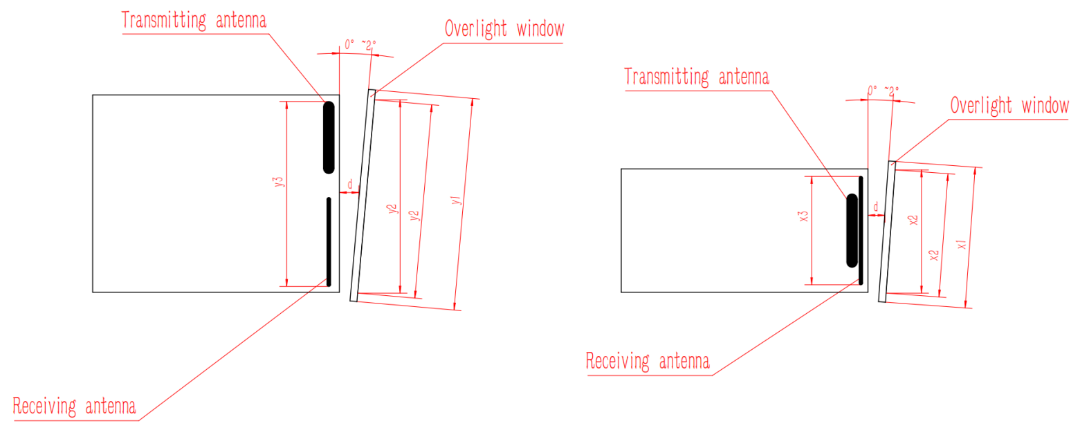
The air gap d between the optical window and the rangefinder should be as small as possibleThe effective aperture of the optical window x2 - the outer diameter of the optical window x1>2mm
The outer diameter of the rangefinder antenna x3-the projection size of the effective aperture of the optical window x2,>1.5mm
The air gap d between the optical window and the rangefinder should be as small as possible
Schematic diagrams of two ways of the external dimensions and placement of the optical window
3. Operation In order for you to fully understand all the functions of this system and correctly master the installation, operation and maintenance methods, please read the content of this chapter carefully before installing and using this system.
3.1 Power-on Operation
3.1.1 Before Power-on
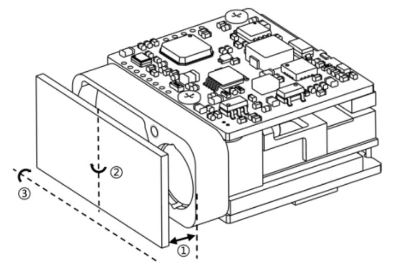
Connect the laser rangefinder, the debugging cable, the DC power supply and the host computer as shown in the figure.
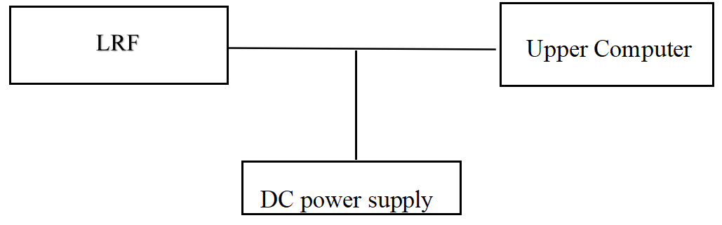
Schematic Diagram of the Connection
3.1.2 Power-on
Power-on operation: Connect the power supply.
3.2 Power-off Operation
3.2.1 Before Power-off
Before powering off, it should be confirmed that the working processes and tasks of each product are in the ended state, and the program is exited.
3.2.2 Power-off
Power-off steps: Disconnect the power supply.
3.3 Operation
3.3.1 Ranging Mode
Operation method of the ranging mode:
a) Send the "Single Ranging" command to the laser rangefinder. The laser rangefinder will perform single ranging and report the ranging status and the distance value.
b) Send the "1Hz Ranging" command to the laser rangefinder. The laser rangefinder will perform ranging once per second and report the ranging status and the distance value.
c) Send the "Stop Ranging" command to stop ranging.
d) Send the "5Hz Ranging" command to the laser rangefinder. The laser rangefinder will perform ranging five times per second and report the ranging status and the distance value.
e) Send the "Stop Ranging" command to stop ranging.
f) Send the "10Hz Ranging" command to the laser rangefinder. The laser rangefinder will perform ranging ten times per second and report the ranging status and the distance value.
g) Send the "Stop Ranging" command to stop ranging.
3.3.2 Distance Gating Setting
Distance gating means setting a section of gating distance (represented in hexadecimal) within the ranging capability range. The target distance information lower than the gating value will not be sent back, and the ranging value higher than the gating value within the measurement range is the effective ranging value.
If setting is required, the operation method is as follows:
a) Send the "Gating Value Setting" command to the laser rangefinder.
Send the "Ranging" command to the laser rangefinder. The laser rangefinder will perform ranging, determine whether the sent-back distance value is greater than the distance gating value, and then report the ranging result.
c) Send the "Stop Ranging" command to stop the ranging operation. If the distance gating function is not needed, the initial settings need to be manually restored (set the gating value to 0).
3.3.3 Self-check Mode
The operation method of the self-check:
a) Send the "Self-check Inquiry" instruction to the laser rangefinder. The laser rangefinder starts to conduct a self-check and sends back information such as the current ambient temperature and working status.
4. Inspection and Maintenance
4.1 General Inspection
Visual inspection and power-on inspection should be carried out when the product is used for the first time and after the resource module is replaced. For products in normal use, only power-on inspection is required before use.
4.1.1 Visual Inspection
The steps of visual inspection are as follows:
a) Check whether the appearance of the product is normal;
b) Check if there is any error in the cable connection, and the connection should be firm.
4.1.2 Power-on Inspection
The steps of power-on inspection are as follows:
a) Complete the power-on operation according to the steps in 3.1;
b) Start the self-test module;
c) After the inspection is completed, complete the power-off operation according to the steps in 3.2.
4.2 Regular Maintenance
The laser rangefinder does not need maintenance under normal working conditions. Maintenance is required if it is stored in a dust-free environment for more than one year. The maintenance content includes:
4.2.1 General Inspection
Conduct a general inspection of the product when it is not energized. The steps are as follows:
a) All marks and numbers on the product and the test cable plug (socket) should be correct and clear;
b) All kinds of screws on the panel should be tightened;
c) It should be ensured that there are no attachments such as light spots, pockmarks, water stains, mold, fingerprints, dust particles, etc. and cracks that hinder normal observation on the optical glass of the product as seen visually.
4.2.2 Power-on Inspection
Conduct a comprehensive inspection and maintenance of the laser rangefinder when it is powered on. The content includes:
a) Turn on the power of the product in sequence;
b) Complete the power-on operation according to the steps in 3.1;
c) Start the product self-test module and complete the product self-test;
d) Complete the power-off operation according to the steps in 3.2.
5. Analysis of Fault Symptoms and Troubleshooting Methods
The laser rangefinder is a precision product. When a fault occurs, the entire device needs to be returned to the factory for fault analysis, location, and repair. Self-repair is not allowed.
Common fault symptoms and troubleshooting methods are shown in the following table.
Common Fault Symptoms and Troubleshooting Methods
| Fault Symptoms | Possible Reasons | Inspection Method | Measures for Troubleshooting |
| The product cannot be powered on normally. | a) Faults in the power supply and connection cables.b) Circuit faults. | Check the power supply and the connection cable. | a) Replace the power supply or the connection cable.b) b) In case of a circuit fault, contact the manufacturer for assistance in solving the problem. |
| Cannot return communication information. | a) Fault of the connection cableb) Abnormal power supplyc) c) Communication fault of the laser rangefinder | a) Check whether the connection cable is normal.b) Check whether the power supply is normal. | a) Replace the connection cable and the power supply. b) For communication problems, contact the manufacturer for assistance in solving them. |
6. Requirements for Packaging, Transportation and Storage
6.1 Packaging
For the products that have been unsealed and need to be restocked, they should be packaged according to the original packaging. When the products need to be returned to the factory, the original packaging should be used as much as possible. When other forms of packaging are used, it should not cause a decrease in product performance or damage to the products.
6.2 Transportation
The products that have been repacked can be transported by means of automobiles, trains, airplanes, ships, etc. During transportation, the packaged items should be fixed on the means of transportation to avoid phenomena such as impact, rough handling, and being exposed to rain and snow. For the road transportation and railway transportation environments, refer to MIL-STD-810G.
6.3 Storage
The repacked products shall not be stored in the open air in the wild. They should be stored in a warehouse with a storage temperature of 0℃ to +30℃, a relative humidity not exceeding 80%, free from the erosion of corrosive substances, strong mechanical vibration and impact, and strong magnetic fields.
Safety Precautions
In order to use this product safely, please read this instruction manual carefully before operating the product.
l This laser rangefinder is a precision optical and mechanical product. Operating it in violation of the regulations may lead to dangerous laser injury. Do not open or adjust any part of the laser rangefinder, and do not attempt to repair or adjust the performance of the laser rangefinder by yourself.
l Pay attention to electrostatic protection: The electronic components of the laser rangefinder are sensitive to electrostatic discharge. Do not touch any electronic devices without protective measures.
l Only turn on the power of the laser rangefinder for operation within the specified voltage and power range.
l It is prohibited to touch the optical lenses with fingers or hard objects (to prevent oil contamination or scratching of the lenses).
l It is prohibited to measure high-reflectivity targets at too close a distance (to prevent damage to core components of the detector, etc.).
l It is prohibited to store the laser rangefinder under non-specified conditions (such as a highly polluted environment, exceeding the storage temperature range, etc.).
l It is prohibited for the laser rangefinder to be subjected to strong mechanical impacts (vibration, impact, dropping, etc.).

OEM/ODM 1-90km LRF Module
Shenzhen Jiguang Technology Co., Ltd
Email: sales@jioptics.com
Website: www.jioptics.com
Address: 2017 Longcheng Avenue, Longgang District, Shenzhen
Hot Tags: 1535nm 3km Miniature Laser Ranging module, Manufacturers, Suppliers, Factory, China, Made in China, Customized, High Quality
Related Category
905nm Laser Range Finder Module
1535nm Laser Range Finder Module
1570nm Laser Range Finder Module
1.54um Laser Rangefinder Module
1064nm Laser Target Designator
Anti drone ststem module
Ranging Lidar Module
Send Inquiry
Please feel free to give your inquiry in the form below. We will reply you in 24 hours.