If you’ve ever tried to integrate distance measurement into a product (UAV payloads, EO/IR devices, industrial optics, smart monitoring, robotics, and more), you already know the ugly truth: the ranging sensor is rarely “just a part.” It’s a systems decision that can make your device feel rock-solid—or painfully unreliable. In this article I’ll break down what a Laser Rangefinder Module really needs to deliver, where integrations usually fail, and how to spec, test, and deploy with fewer surprises. I’ll also reference how manufacturers like Shenzhen Jioptics Technology Co., Ltd. position modules for OEM integration—without copying anyone’s page.
Abstract
A Laser Rangefinder Module can solve a deceptively hard problem: reliable distance measurement across real-world targets, lighting, weather, and motion. But buyers often get burned by vague “range” claims, overlooked interface details, power and thermal constraints, and weak validation on their exact target surfaces. This blog provides an integration-first checklist, selection framework, test plan, and FAQs—designed to reduce risk, shorten development cycles, and improve performance in the field.
Table of Contents
- Outline
- What Pain Points Do Buyers Actually Have?
- What Is a Laser Rangefinder Module in System Terms?
- How Do I Choose the Right Module Without Guessing?
- Which Specs Matter Most in Real Deployment?
- What Integration Mistakes Cause 80% of Failures?
- What Validation Test Plan Should I Run Before Scaling?
- Where Do Laser Rangefinder Modules Usually Deliver the Most Value?
- FAQ
- Next Steps
Outline
- Define success: “reliable distance” vs “maximum range”
- Build a selection matrix around targets, environment, and integration constraints
- Prioritize interface, timing, and error behaviors as much as optics
- Run a field-like test plan before committing to production
- Document EEAT evidence: test results, calibration notes, traceability, and support readiness
What Pain Points Do Buyers Actually Have?
When someone tells me, “We need a Laser Rangefinder Module,” they usually mean, “We need distance data we can trust without rewriting the product plan.” The pain points tend to cluster into a few predictable buckets:
- Range confusion: marketing range vs. range on your target size/material vs. range in your weather/light.
- Integration surprises: interface levels, timing jitter, output formats, and error codes that weren’t defined clearly.
- Power/thermal constraints: peak current and heat dissipation that break battery life or cause drift.
- “Works in the lab” syndrome: great demo results, unstable field results due to motion, vibration, haze, or background light.
- Supply and support risk: inconsistent build, calibration variance, or weak documentation that slows production.
If you’re nodding right now, good—you’re not “picky,” you’re paying attention. A rangefinder is a measurement instrument, not a toy.
What Is a Laser Rangefinder Module in System Terms?
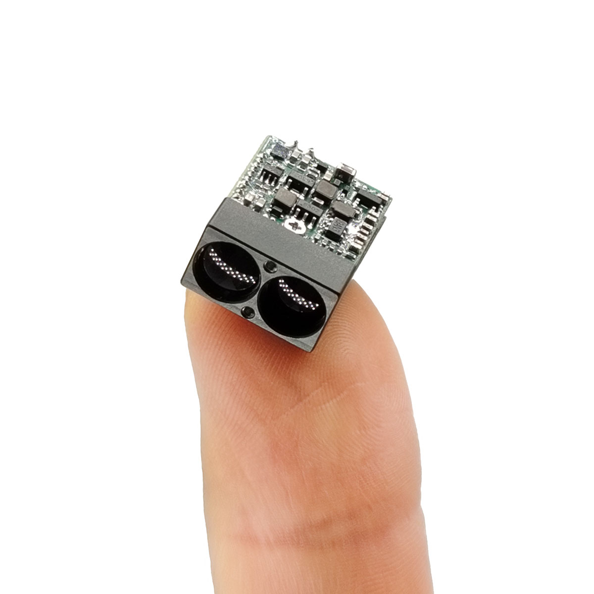
In system terms, a Laser Rangefinder Module is a tightly-coupled stack of:
- Emitter + optics: sends a laser pulse/beam toward the target.
- Receiver + filtering: detects the return signal and rejects noise.
- Timing/ToF logic: measures round-trip time to estimate distance.
- Firmware + output protocol: formats results, provides modes (single, continuous, multi-target), and defines error behavior.
- Mechanical + thermal design: keeps alignment stable and performance consistent across temperature, vibration, and runtime.
This is why “drop-in replacement” claims can be risky: even if dimensions match, the timing, filtering, and firmware assumptions may not.
How Do I Choose the Right Module Without Guessing?
I recommend selecting a Laser Rangefinder Module using a “target + environment + integration” matrix rather than chasing the biggest kilometer number. Below is a simple decision table you can adapt for procurement and engineering reviews.
| Selection Factor | What to Define | Why It Matters |
|---|---|---|
| Target | Size, reflectivity, angle, movement | Real range depends heavily on what you’re measuring |
| Environment | Sunlight/background, haze/fog/dust, rain, temperature | Noise and attenuation drive dropouts and false readings |
| Measurement Mode | Single vs continuous, multi-target, first/last target | Different apps need different behaviors and filtering |
| Interface | UART/serial, voltage levels, timing, packet format | Integration cost often lives here, not in optics |
| Power & Thermal | Peak current, average draw, heat dissipation plan | Prevents brownouts, drift, and runtime limits |
| Manufacturing Readiness | Calibration, traceability, documentation, support | Reduces production variance and field returns |
Manufacturers such as Shenzhen Jioptics Technology Co., Ltd. often emphasize OEM integration and multiple distance-class options across product lines, which is exactly what you want to see when you’re planning for scale rather than a one-off prototype. :contentReference[oaicite:0]{index=0}
Which Specs Matter Most in Real Deployment?
Here’s my “don’t get fooled” list—these are the specs and behaviors that actually control success for a Laser Rangefinder Module:
- Confidence & error behavior: Do you get quality indicators, and do failures fail loudly (clear error) instead of silently (wrong distance)?
- Repeatability under motion: Stable readings with vibration, fast panning, or platform movement.
- Minimum range and near-field behavior: Many applications break at close distances, not far distances.
- Update rate and latency: Control loops and tracking care more about timing than raw max range.
- Environmental robustness: How quickly performance degrades in haze, dust, and high background light.
- Alignment tolerance: Small misalignment can become “range instability” in the field.
For EEAT, don’t just repeat datasheets. Keep internal test logs showing your target types, distances, conditions, and pass/fail thresholds. That evidence becomes your credibility when customers ask, “Will it work for my scenario?”
What Integration Mistakes Cause 80% of Failures?
If I had to be a little ruthless: most failures aren’t “laser physics,” they’re integration shortcuts. Here are common traps:
1) Assuming “serial is serial”
- Voltage levels and logic expectations differ (TTL vs other). Don’t guess—verify and document.
- Define packet format, checksum strategy, and version control for firmware updates.
2) Power delivery that looks fine on paper
- Peak current spikes can cause resets or bad readings—especially on batteries.
- Separate the “module works” test from the “module works inside my system” test.
3) Mechanical mounting without respect for optics
- Vibration, micro-shifts, and thermal expansion can change alignment.
- Plan for stable mounting points and consistent thermal paths.
4) No “bad target” strategy
- Dark, angled, or low-reflective surfaces can reduce return signal dramatically.
- Your UI/logic needs a fallback when confidence drops: retry rules, smoothing, or mode switching.
What Validation Test Plan Should I Run Before Scaling?
Here’s a practical validation plan I like for a Laser Rangefinder Module. It’s simple, it’s measurable, and it exposes unpleasant truths early:
- Target matrix: test at least 6 target types (bright/neutral/dark, matte/glossy, flat/angled, small/large).
- Distance sweep: verify accuracy and dropout rate at near, mid, and far distances relevant to your product.
- Lighting sweep: indoor, outdoor shade, outdoor strong background light.
- Motion/vibration: shake table or platform movement; measure stability and latency.
- Thermal soak: cold start + warmed steady state; log drift behavior.
- EMI sanity check: run alongside radios, motors, and switching regulators (the usual troublemakers).
- Firmware behaviors: verify error codes, timeout handling, and “no return” behavior.
If you want to look credible under EEAT, publish what you can: a simplified test method, what you measured, and what “good” means in your application. That’s the difference between “marketing copy” and actual authority.
Where Do Laser Rangefinder Modules Usually Deliver the Most Value?
A Laser Rangefinder Module earns its keep when distance directly improves decision-making or user confidence. Common high-value scenarios include:
- UAV payloads and gimbals: standoff distance, navigation support, target tracking workflows.
- EO/IR and thermal devices: range overlay, identification support, and operational clarity in low visibility.
- Industrial measurement: spot checks where mechanical measurement is slow or unsafe.
- Robotics and monitoring: simple, direct distance channels that complement vision systems.
If you’re building any of the above, your selection process should prioritize repeatability, error behavior, and integration stability—because that’s what customers experience.
FAQ
What is the difference between “maximum range” and “usable range”?
Maximum range is usually measured on favorable targets in controlled conditions. Usable range is what you consistently achieve on your real target types under your real lighting, weather, and motion. For product reliability, usable range is the only number that matters.
Why do some targets fail even at short distances?
Low reflectivity, steep angles, specular surfaces, and complex backgrounds reduce return signal quality. A good integration plan includes confidence handling, retry logic, and clear “no return” behavior.
How do I reduce integration time with a Laser Rangefinder Module?
Start by locking down interface requirements (voltage levels, protocol, timing, error codes), then validate power integrity under peak loads, and finally test on your actual targets. Don’t treat these as “later” tasks—this is where schedule risk lives.
What should I ask a supplier before purchasing?
- What target definition is used for the range claim?
- What are the output modes and how are failures reported?
- What is the recommended power design and thermal guidance?
- What documentation is provided (protocol, mechanical, test notes, calibration approach)?
- What is the plan for firmware updates and version traceability?
Is ToF always the right approach?
Time-of-flight approaches are very common for practical rangefinding because they map well to robust distance measurement workflows. Whether it’s “right” depends on your constraints: environment, range, update rate, power, and cost. Choose based on your application truth, not buzzwords.
Next Steps
If you want your next integration to feel predictable (instead of “hope-based engineering”), define your target/environment matrix, run a small validation plan, and select a Laser Rangefinder Module based on usable performance and integration clarity.
Working with teams like Shenzhen Jioptics Technology Co., Ltd. can make sense when you need an OEM-minded supplier and a module lineup oriented to integration outcomes. :contentReference[oaicite:1]{index=1}
Ready to share your target type, operating conditions, and integration constraints? Contact us today and let’s match the right module and validation approach to your real use case—faster, cleaner, and with fewer field surprises.