Home
>
Products > Laser Rangefinder Module > 1064nm Laser Target Designator > 25mJ 1064nm Laser Target Designator


25mJ 1064nm Laser Target Designator
The STA-106425M medium laser photometer (hereinafter referred to as the laser photometer) is a precision photoelectric product which transmits the laser to a specific target and calculates the distance information according to the laser flight time. The 25mJ 1064nm Laser Target Designator has the characteristics of outstanding performance and simple operation.
Model:JIO-106425M
Send Inquiry
Product Description
25mJ 1064nm Laser Target Designator TECHNICAL SPECIFICATIONS
| PERFORMANCE SPECIFICATIONS | |
| Laser wavelength | 1.064μm |
| Pulse average energy | ≥25mJ |
| Pulse capacity fluctuation | within a cycle, adjacent pulse fluctuation ≤8%(statistics after 2 seconds of light output) |
| Laser beam dispersion Angle | ≤0.5mrad |
| Laser optical axis stability | ≤0.05mrad |
| Pulse width | ≤20ns |
| Power-on preparation time | ≤3s |
| RANGING PERFORMANCE | |
| Ranging frequency | 1Hz, 5Hz, single time |
| Continuous ranging time | 5min(1Hz), 1min(5Hz) |
| 5Hz maximum continuous operating time | 2min |
| Minimum range | ≤100m |
| Typical ranging capacity | ≥2000m |
| Ranging accuracy | ±2m |
| Accurate measurement rate | ≥ 98% |
| Ranging logic: first and last target | first and last target |
| IRRADIATION PERFORMANCE | |
| Irradiation distance | ≥2km |
| Irradiation frequency | fundamental frequency 20Hz |
| Coding | in line with system requirements; With the ability to customize coding extension |
| Encoding mode | precise frequency code |
| Encoding accuracy | ≤±2.5μs |
| Irradiation mode | one irradiation time ≥20s, start irradiation again, interval ≤15s, can be continuously irradiated for 8 cycles |
| WEIGHT AND SIZE | |
| Weight | ≤450g |
| Size | ≤67.4mm×51mm×90mm |
| POWER SUPPLY VOLTAGE | |
| Voltage | 19.6V ~ 25.2V |
| POWER CONSUMPTION | |
| Standby power consumption | ≤4W |
| Average power consumption | ≤50W |
| Peak power consumption | ≤90W |
| ENVIRONMENTDL ADAPTABILITY | |
| Working temperature | -40℃ ~ 55℃ |
| Storage temperature | -55℃ ~ 70℃ |
CONTROL FUNCTION
2.1 With laser ranging function;
2.2 Provide target laser irradiation;
2.3 Be able to communicate with the host computer according to the requirements of the communication protocol.
The laser imager can realize the following functions through the serial communication interface:
2.3.1 Response laser ranging instruction, and can be stopped at any time according to the stop instruction;
2.3.2 Distance data and state information are output per pulse when ranging;
2.3.3 Ranging with distance gating function;
2.3.4 Start continuous ranging did not receive stop instruction 5min(1Hz)/1min(5Hz) after the automatic stop ranging;
2.3.5 Irradiation mode and coding can be set;
2.3.6 In response to the laser irradiation command, according to the mode, encoding, irradiation has been set, and can stop irradiation at any time according to the stop instruction;
2.3.7 If no stop instruction is received after starting irradiation, it will stop automatically after one cycle of irradiation;
2.3.8 When the laser irradiation, each pulse output a distance value and state information;
2.3.9 Power-on self-check and cycle self-check and output status information;
2.3.10 Respond to start self-check instruction and output status information;
2.3.11 Able to report the cumulative number of laser pulses;
2.3.12 Head and end target ranging function.
MECHICAL INTERFACE
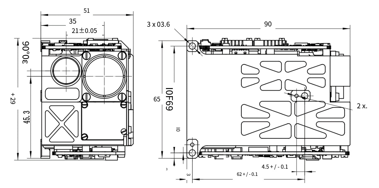
Figure 1 Interface diagram
COMMUNICATION PROTOCOL
4.1 Communication Protocol Definition
4.1.1 Asynchronous serial communication standard: RS422;
4.1.2 Baud rate: 115200bps;
4.1.3 Transmission format: 8 data bits, 1 start bit, 1 stop bit, no check bit;
4.1.4 For each byte of information, the lowest position (lsb) is transmitted first, and if it is a multi-byte message, the lowest byte is transmitted first.
4.2 The command sent by the upper computer system to the laser photometry module
4.2.1 Information header (0x55);
4.2.2 Command word 1;
4.2.3 Command word 2;
4.2.4 Command word 3;
4.2.5 The "message tail" is the checksum, the result of the xor operation of 1-4 bytes.
Table 1Command word 1 definition
| BIT07 | BIT06 | BIT05 | BIT04 | BIT03 | BIT02 | BIT01 | BUT00 |
|
0x00: Standby 0x01: Start self-test 0x02: Single ranging 0x03: Continuous Ranging (1Hz) 0x04: Continuous Ranging (5Hz) 0x05: Irradiation 0x08: Stop ranging/Irradiation 0x09: Gate setting 0xAA: Reports the cumulative number of laser pulses |
|||||||
Table 2 Command word 2 definition
| BIT07 | BIT06 | BIT05 | BIT04 | BIT03 | BIT02 | BIT01 | BUT00 |
|
When illuminated by laser: Laser code 1 to 8 When laser ranging: 1- first target 2- end target When the gating value is set: The distance gating value is low in bytes |
|||||||
Table 3 Command word 3 Define
| BIT07 | BIT06 | BIT05 | BIT04 | BIT03 | BIT02 | BIT01 | BUT00 |
|
Fast hair: Laser exposure time setting (1 ~ 47) When the gating value is set: the distance gating value is high in bytes |
|||||||
4.3 The laser photometer sends data to the system software
4.3.1 Information header (0x55);
4.3.2 Status word;
4.3.3 Target distance/cumulative number of laser pulses (2 bytes);
4.3.4 Current temperature of laser measuring module;
4.3.5 The "message tail" is the checksum, which is the xor operation result of 1-5 bytes.
4.3.1 Information header (0x55);
4.3.2 Status word;
4.3.3 Target distance/cumulative number of laser pulses (2 bytes);
4.3.4 Current temperature of laser measuring module;
4.3.5 The "message tail" is the checksum, which is the xor operation result of 1-5 bytes.
Table 4Information header description
| BIT07 | BIT06 | BIT05 | BIT04 | BIT03 | BIT02 | BIT01 | BUT00 |
|
0: No laser 1: Laser is present |
0: Ranging effective 1: Ranging invalid |
Laser mark 1/0 alternate |
1: Overtemperature alarm 0: The temperature is normal |
|
|
00: Standby 01: Ranging 02: Indication |
|
Target distance information Definition: The distance value is represented as an integer by 2 bytes (16BIT), which can be converted directly to decimal.
Cumulative laser pulse times definition: because the range of 16 bits of binary number is 0 ~ 65535, and the service life of the laser detector is one million times, so the agreed laser emission times for the multiple of the number of 20, the range is 0 ~ 1310700;
Laser measuring module current temperature: d7-d0: complement expression, value range -128℃ ~ +127℃.
ELECTRICAL INTERFAC
One RS422 interface, signal level in line with MAX488 chip characteristics. The interface definition is shown in Table 5:
Table 5 Interface definition
| Socket MOLEX 53048-0810 | ||
| Corresponding plug MOLEX 51021-0800 | ||
| Pin number | Signal name | Instructions |
| 1 | 24V | Power supply + |
| 2 | 24V | Power supply + |
| 3 | 24VGND | Power supply - |
| 4 | 24VGND | Power supply - |
| 5 | 422_A | Upper computer -> Laser photometry Assembly + |
| 6 | 422_B | Upper computer -> Laser photometric Assembly - |
| 7 | 422_Z | Laser photometry Assembly -> Upper computer - |
| 8 | 422_Y | Laser photometry Assembly -> Upper computer + |
| Socket MOLEX 530480210 | ||
| Corresponding plug MOLEX 151340201 | ||
| Pin number | Signal name | Instructions |
| 1 | SYNC_IN+ | The external sync_in signal is a differential signal with an interface type of RS422 |
| 2 | SYNC_IN- | |
Hot Tags: 25mJ 1064nm Laser Target Designator, Manufacturers, Suppliers, Factory, China, Made in China, Customized, High Quality
Related Category
905nm Laser Range Finder Module
1535nm Laser Range Finder Module
1570nm Laser Range Finder Module
1.54um Laser Rangefinder Module
1064nm Laser Target Designator
Anti drone ststem module
Ranging Lidar Module
Send Inquiry
Please feel free to give your inquiry in the form below. We will reply you in 24 hours.


 wiht LRF")
 wiht LRF")