Home
>
Products > Laser Rangefinder Module > 1064nm Laser Target Designator > 45mJ Laser Target Designator(LTD) wiht LRF


 wiht LRF")
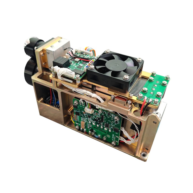
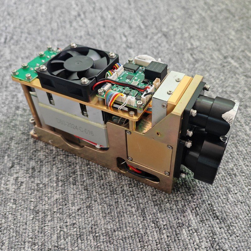
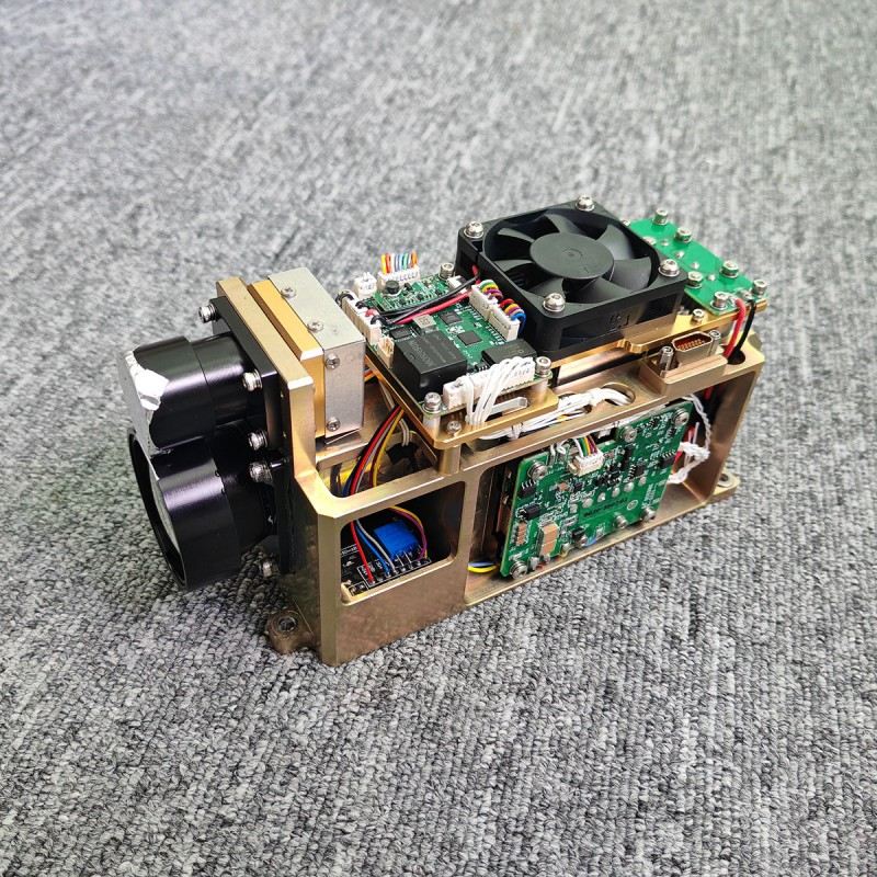
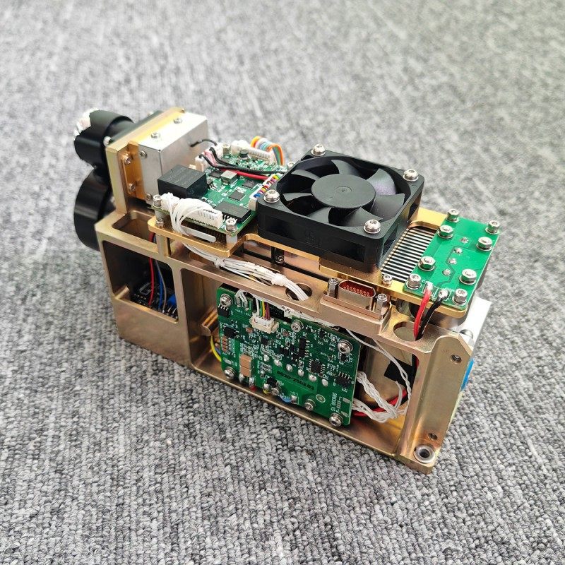
45mJ Laser Target Designator(LTD) wiht LRF
STA-B45M is a military 45mj laser target designator that plays a crucial role in precision aiming systems, capable of providing precise guidance for smart ammunition. Through an advanced optical system, it marks the target with a laser beam, ensuring that precision-guided weapons can destroy the target with extremely high accuracy and efficiency.
Send Inquiry
Product Description
Product Features
Lightweight and miniaturized
Environmental adaptability: -40 ℃~60 ℃ wide temperature adaptability
Environmental adaptability: -40 ℃~60 ℃ wide temperature adaptability
Core indicator parameters
Function
a) It has the function of setting the irradiation cycle and can perform laser irradiation according to the set cycle.
b) Equipped with laser single and repeated ranging functions.
c) Equipped with multi-target ranging function.
d) Equipped with temperature output function for the core components of the camera.
e) Equipped with overheat protection function for the measuring device.
f) Equipped with the function of outputting status information of the lighting device.
Technical parameters
| Model | STA-B6445M |
| Laser wavelength | 1.06um (using Nd: YAG crystal, design selection guarantee) |
| Laser average energy | ≥ 45mJ (energy fluctuations ≤ ± 8%); |
| laser divergence angle | ≤ 0.5mrad |
| laser emission optical axis stability | ≤ 0.05mrad |
| laser emission optical axis and the installation of the base plane is not parallel | ≤ 3' (design guarantee); |
| Laser pulse width | 10ns ~ 22ns |
| Max Ranging | Visibility ≥ 12km, maximum range for measuring NATO targets ≥ 6km; |
| Mini Ranging | 100m |
| Ranging repeat frequency | 1hz/5hz/single |
| Ranging accuracy | ≤ ± 2m (RMS) |
| ranging accuracy | ≥ 98% |
| Distance resolution | ≤ 50m |
| Continuous ranging working time | 5min (5Hz: continuous work 5min, rest ≤ 3min, can continue to range). |
| Maximum irradiation distance | ≥ 5km |
| Minimum irradiation distance | ≤ 500m (with the system assessment) |
| Continuous irradiation cycle | 8, each cycle lasts 25s, with 15s interval; after 8 cycles, rest interval ≤ 20 min; |
| Laser code period (set by communication protocol) | setting range 40ms~100ms |
| Laser coding timing accuracy | ≤±2μs |
| Laser start-up time | ≤3min |
| Extra-code synchronisation function | Yes |
| Working temperature: | -40~+60℃ |
| Storage temperature | -50~+70℃ |
| Weight | ≤580g |
| Modul Size | 138x75x50mm |
| with multi-target measurement capability, and return three multi-target value, with distance selective pass function.Frequency code and variable interval code can be set (set by communication protocol). | |
Preparation for use
Check whether the power supply voltage is between 18V and 32V. When the voltage is too low (less than 18V), the rangefinder may not communicate correctly or indicate ‘no laser output’, and when the voltage is too high (more than 32V), the whole illuminator may be permanently damaged. Ensure that the rated output current of the power supply system is greater than 6A, if it is less than this value, there may be no laser during operation. Ensure that the polarity of the power supply is correctly connected, there is a risk of damage to the equipment if the polarity is reversed. See Appendix A for definitions of power supply sockets.
Precautions for use
a) The laser emitted by this rangefinder is a 1.06µm non-eye safe wavelength laser, avoid direct laser light to the eyes when using.
b) When adjusting the parallelism of the optical axis, be sure to block the receiving lens, otherwise the detector will be permanently damaged due to the strong echo.
c) This rangefinder module is non-airtight, be sure to use the environment relative humidity is less than 80%, and ensure that the use of environmental cleanliness and hygiene, so as not to damage the laser.
d) The range of the rangefinder is related to the atmospheric visibility and the nature of the target, in the case of fog, rain and wind and sand ranging will reduce the range. Targets such as green leaf clusters, white walls and exposed limestone have better reflectivity and can increase range. In addition, an increase in the inclination of the target to the laser beam will reduce range.
e) It is strictly prohibited to fire the laser beam at strongly reflective targets such as glass and white walls within 100 metres to avoid strong echoes, which may cause damage to the APD detector.
f) It is strictly prohibited to unplug or plug the cable while it is energised.
g) Make sure that the power polarity is correctly connected, otherwise it will lead to permanent damage to the device.
Definition of interface sockets
Table 1 Definition of external interfaces
Table 1 Definition of external interfaces
| Order number | Interface type | Pigment | Definition | Remarks |
| 1 | DB9 interface definition | Palm | RS422 T+ | RS422 communication interface |
| 2 | Purple | RS422 T- | ||
| 3 | Yellow | RS422 R- | ||
| 4 | Green | RS422 R+ | ||
| 5 | White | GND | ||
| 6 | Ash | External trigger- | RS422 level | |
| 7 | Blue | External trigger + | ||
| 8 | Definition of power interface | Black | VCC+ | DC 18V~32V |
| 9 | Red | VCC- |
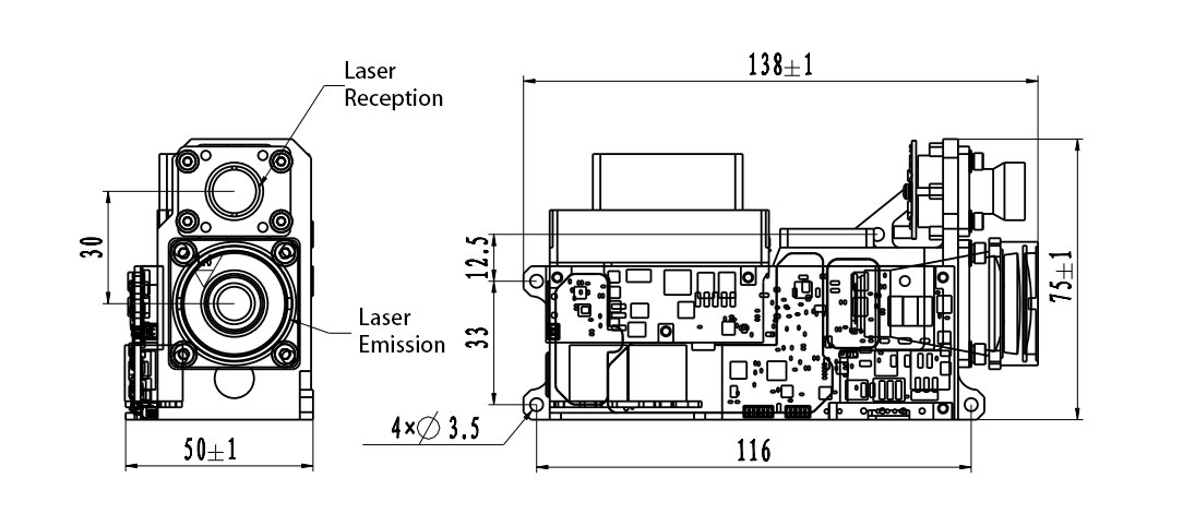
Figure 2 Two-dimensional size diagram of the product
Interface communication protocol
1.Communication format:
a)The default baud rate is 115200bps.
b)Data format: 8-bit data, one start bit, one stop bit, no parity check, data consists of header byte, command part, data length, parameter part and check byte.
2.communication mode:
a)The master and the measuring device use the master-slave communication mode, in which the master sends control commands to the measuring device and the measuring device receives and executes the instructions. In the ranging state, the measuring device sends the data and status of the measuring device back to the upper computer according to the ranging period, and the communication format and command content are shown in the following table.
b)After the master sends the control command, the meter continuously responds with three response commands. If the master does not receive the response command from the meter within the time limit, it will resend it again.
The format of the message to be sent is as follows
| STX0 | CMD | LEN | DATA1H | DATA1L | CHK |
Table 2 Format description of the message sent
| order number | name | explain | code | remarks |
| 1 | STX0 | Message start flag | 55(H) |
|
| 2 | CMD | CW | See table 3 |
|
| 3 | LEN | DL | The number of all bytes except the start mark, command word, and checksum |
|
| 4 | DATAH | parameter | See table 3 |
|
| 5 | DATAL |
|
||
| 6 | CHK | XOR verification | Except for the valid byte, all other bytes are XORed |
|
The command is described as follows:
Table 3 Description of commands and data words sent by the master to the meter
Table 3 Description of commands and data words sent by the master to the meter
| order number | CW | function | data byte | remarks | length | Example code |
| 1 | 0x00 | Stop (stop ranging illumination) | D1=00(H)D0=00(H) |
|
Six bytes | 55 00 02 00 00 57 |
| 2 | 0x01 | Single ranging | D1=00(H)D0=00(H) | The measuring device receives a single ranging instruction, performs a ranging operation and uploads the ranging distance value at the same time; | Six bytes | 55 01 02 00 00 56 |
| 3 | 0x02 | Continuous ranging | D1=XX(H)D0=YY(H) | According to the set ranging period, the ranging distance value is uploaded continuously. DATA expresses the ranging period, and the unit is ms | Six bytes | 55 02 02 03 E8 BE(1Hz ranging) |
| 4 | 0x03 | self-checking | D1=00(H)D0=00(H) |
|
Six bytes | 55 03 02 00 00 54 |
| 5 | 0x04 | Blind zone setup | D1=XX(H)D0=YY(H) | DATA describes the blind zone value, unit 1m, and sets the distance display within the blind zone to 0; | Six bytes | 55 04 02 01 2C 7E(300m is the closest distance) |
| 6 | 0x06 | Cumulative number of light output queries | D1=00(H)D1=00(H) | Power off storage; | Six bytes | 55 06 02 00 00 51 |
| 7 | 0x31 | Set the precise code | D4 D3~D0 | D4: precise code number, built-in 8 groups, numbered 1~8;D3~D0 represents the pulse period, unit usRange: 45000~60000 | Nine bytes | 55 31 05 01 00 00 c3 50 f3(Precise code number: 1Cycle: 0000c350=50000us) |
| 8 | 0x32 | Set variable interval codes | D33 (ref.)D32 (number of coding bits)D31~D30 (time interval between the last bit 0)D29~D28 (time interval between bit 14 and bit 15)D27~D26 (time interval between bit13 bit14)D25~D24 (time interval between bit 12 and bit 13)D23~D22 (time interval between bit11 bit12)D21~D20 (time interval between bit10 bit11)D19~D18 (time interval between bit9 bit10)D17~D16 (time interval between bit8 bit9)D15~D14 (time interval between bit7 bit8)D13~D12 (time interval between bit6 and bit7)D11~D10 (time interval between bit5 bit6)D9~D8 (time interval between bit4 bit5)D7~D6 (time interval between bit3 bit4)D5~D4 (time interval between bit2 bit3)D3~D2 (time interval between bit1 bit2)D1~D0 (time interval between bit0 and bit1) | D33: variable interval code number, built-in 16 groups, the number range is 1~16;D32: Number of coding bits, ranging from 3 to 16Time interval unit usRange: 45000~60000 | 38 bytes |
|
| 9 | 0x33 | Setting of pseudo-random codes | D4 D3~D0 | D4: pseudo-random code coding, with 2 built-in groups, numbered from 1 to 2;D3: Length of pseudo-random code, ranging from 2 to 16D2 D1: Initial value of pseudo-random code, which is taken from the lower bit according to the length of pseudo-random codeD0: standby, set 0 | Nine bytes | 55 33 05 01 10 aa aa 00 72(Pseudo-random code number: 1Pseudo random code length: 16Initial value:aaaa) |
| 10 | 0x41 | Set the query for precision codes | D1 D0 | D1: precise code number, the number range is 1~8D0: standby, set 0 | Six bytes | 55 41 02 01 00 13Set the query for Precision Code 1 |
| 11 | 0x42 | Set the query for variable interval codes | D1 D0 | D1: Variable interval code number, the number range is 1~16D0: standby, set 0 | Six bytes | 55 42 02 01 00 14Set the query for variable encoding 1 |
| 12 | 0x43 | Set up a query for pseudo-random codes | D1 D0 | D1: Pseudo-random code number, the number range is 1~2D0: standby, set 0 | Six bytes | 55 43 02 01 00 15Set the query with pseudo-random coding 1 |
| 13 | 0x44 | Continuous irradiation working time setting | D1=00(H)D0=YY(H) | YY continuous irradiation time refers to the continuous working time of the meter under the continuous irradiation mode, unit s. The automatic stop will be stopped after timeout | Six bytes | 55 44 02 00 3C 2FContinuous working time 60s |
| 14 | 0x45 | Continuous irradiation working time query | D1=00(H)D0=00(H) |
|
Six bytes | 55 45 02 00 00 12 |
| 15 | 0x30 | Precise code irradiation | D3~D0 | D3: irradiation mode, 00 continuous irradiation, 01 periodic irradiationD2: 01 precise code irradiationD1: precise code numberD0: Standby 00 | Eight bytes | 55 30 04 00 01 01 00 61Code 1, continuous illumination of precise code |
| Variable interval code irradiation | D3~D0 | D3: irradiation mode, 00 continuous irradiation; 01 periodic irradiationD2:02 Variable interval code irradiationD1: Variable interval code numberD0: Standby 00 | Eight bytes | 55 30 04 00 02 01 00 62Code 1, variable interval code continuous irradiation | ||
| External synchronous irradiation | D3~D0 | D3: 00 External synchronization is only continuous illuminationD2: 03 external synchronous irradiationD1:00D0:00 | Eight bytes | 55 30 04 00 03 00 00 62 | ||
| Pseudo-random code irradiation | D3~D0 | D3: irradiation mode, 00 continuous irradiation; 01 periodic irradiationD2:04 Pseudo-random code irradiationD1: Pseudo-random code numberD0: Standby 00 | Eight bytes | 55 30 04 00 04 01 00 64Code 1, pseudo-random code continuous irradiation | ||
| 16 | 0x24 | Periodic irradiation parameter setting | D2 D1 D0 | D2: Number of working cyclesD1: Working time per cycle, unit sD0: Rest time per cycle, in s | Seven bytes | 55 24 03 08 14 0A 64(8 cycles, 20s work and 10s rest per cycle) |
| 17 | 0x25 | Periodic irradiation parameter query | D1=00(H)D0=00(H) |
|
Six bytes | 55 25 02 00 00 72 |
| 18 | 0xEB | Equipment number query | D1=00(H)D0=00(H) |
|
Six bytes | 55 EB 02 00 00 BC |
| 19 | 0x51 | Debug mode | D1 D0 | D1: 01 Enter debugging mode, 00 exit debugging modeD0: Standby | Six bytes | 55 41 02 01 00 17Enter debug mode55 41 02 00 00 16Exit debug mode |
|
|
|
|
|
|
|
|
a)Main control receives format
The format of the received message is as follows:
The format of the received message is as follows:
| STX0 | CMD | LEN | DATAn | DATA0 | CHK |
Table 4 Format description of received messages
| order number | name | explain | code | remarks |
| 1 | STX0 | Message start flag 1 | 55(H) |
|
| 2 | CMD_JG | Data command word | See table 5 |
|
| 3 | LEN | DL | The number of all bytes except the start mark, command word and checksum |
|
| 4 | Dn | parameter | See table 5 |
|
| 5 | D0 |
|
||
| 6 | CHK | XOR verification | Except for the valid byte, all other bytes are XORed |
|
Main control receiving status description:
Table 5 describes the data word sent by the meter to the master
Table 5 describes the data word sent by the meter to the master
| order number | CW | function Feedback (corresponding to the control command received by the measuring device) | data byte | remarks | overall length |
| 1 | 0x00 | Stop (stop ranging illumination) | D1=00(H)D0=XX(H) | XX: 00 Normal stop01 Stop at high temperature02 Stop when overdue | Six bytes |
| 2 | 0x03 | self-checking | D8 ~D0C5~C0B2~B0 | D8-D7 (int type): -5V voltage value feedback, unit 0.01V.D6-D5: Feedback of blind spot setting value, unit 1mD4-D3: APD high voltage feedback, unit V;D2: char type, indicating the main control environment temperature (environment), unit: degrees Celsius;D1-D0: +5V voltage feedback, unit 0.01VC5-C4: Actual drive current value feedback unit AC3-C2: Set the feedback of drive current value in unit AC1-C0: temperature control temperature feedback unit 0.1℃B2: Drive temperature control status (8bit)Bit0: 0 temperature control to temperature 1 not reachedBit1: 0 temperature control is normal 1 temperature control is overcurrentBit2: The drive current is normal 1. Drive current overcurrentBit3: The drive voltage is normal 1. Drive voltage overvoltageBit4: The drive current and set value are normal 1 The difference between the drive current and the set value is greater than 5AB1: Drive communication status (measuring the communication status between the main control board and the drive module)0 is normal and 1 is faultBit0: Set whether the current is successfulBit1: Whether the pulse width is set successfullyBit2: Set whether the external trigger is successfulBit3: Whether the driver starts successfullyBit4: Whether the driver stop is successfulBit5: Set whether the internal trigger is successfulBit6: SpareBit7: Drive queryB0: Temperature control communication status (communication status between the main control board and the temperature control module)0 is normal and 1 is faultBit0: Whether the temperature control start is successfulBit1: Whether the temperature control stop is successfulBit2: Whether the temperature setting is successfulBit3: Whether the temperature control query is successfulBit4: SpareBit5: SpareBit6: SpareBit7: Spare | 22 bytes |
| 3 | 0x04 | Blind zone setting, unit m | D1 D0 | DATA describes the nearest distance value, unit 1m;Start high and end low | Six bytes(Drop power saving) |
| 4 | 0x06 | Cumulative number of light output queries | D3~D0 | DATA expresses the number of lights, 4 bytes, with the high byte first | Eight bytes |
| 5 | 0x31 | Set the precise code | D4 D3~D0 | D4: precise code number, range 1~8D3~D0 represents the period, unit usRange: 45000~60000 | Nine bytes |
| 6 | 0x32 | Set variable interval codes | D1 D0 | D1 variable interval code number range 1~16D0 00 is set successfully, and 01 is set failed | Six bytes |
| 7 | 0x33 | Set a pseudo-random code | D1 D0 | D1 pseudo-random code number range 1~2D0 00 is set successfully, and 01 is set failed | Six bytes |
| 8 | 0x41 | Precise code cycle query | D4 D3~D0 | D4: precise code number, range 1~8D3~D0 represents the period, unit usRange: 45000us~60000us | Nine bytes |
| 9 | 0x42 | Variable interval code query | D33 (ref.)D32 (number of coding bits)D31~D30 (time interval between the last bit 0)D29~D28 (time interval between bit14 bit15)D27~D26 (time interval between bit13 bit14)D25~D24 (time interval between bit 12 and bit 13)D23~D22 (time interval between bit 11 and bit 12)D21~D20 (time interval between bit 10 and bit 11)D19~D18 (time interval between bit9 and bit10)D17~D16 (time interval between bit8 bit9)D15~D14 (time interval between bit 7 and bit 8)D13~D12 (time interval between bit6 bit7)D11~D10 (time interval between bit5 bit6)D9~D8 (time interval between bit4 and bit5)D7~D6 (time interval between bit3 bit4)D5~D4 (time interval between bit2 bit3)D3~D2 (time interval between bit1 bit2)D1~D0 (time interval between bit0 bit1) |
|
38 bytes |
| 10 | 0x43 | Pseudo-random code query | D4 D3~D0 | D4: pseudo-random code coding, range 1~2D3: Length of pseudo-random code, ranging from 2 to 16D2 D1: Initial value of pseudo-random code, which is taken from the lower bit according to the length of pseudo-random codeD0: standby, set 0 | Nine bytes |
| 11 | 0x44 | Continuous irradiation working time setting | D1=00(H)D0=YY(H) | YY continuous irradiation time, unit s, timeout automatically stop | Six bytes |
| 12 | 0x45 | Continuous exposure working time query | D1=00(H)D0=YY(H) | YY continuous irradiation time, unit s, timeout automatically stop | Six bytes |
| 13 | 0x24 | Periodic irradiation parameter setting | D2 D1 D0 | D2: Number of working cyclesD1: Working time per cycle, unit sD0: Rest time per cycle, in s | Seven bytes |
| 14 | 0x25 | Periodic irradiation parameter query | D2 D1 D0 | D2: Number of working cyclesD1: Working time per cycle, unit sD0: Rest time per cycle, in s | Seven bytes |
| 15 | 0xEB | Equipment number query | D15~D0 | D15~D12: Product modelD11 D10: Product numberD9 D8: Software versionD7 D6: Adjust Q numberD5 D4: Drive numberD3 D2: Laser numberD1 D0:FPGA ID | 20 bytes |
| 16 | 0x51 | Debug mode | D1 D0 | D1: 01 Enter debugging mode, 00 exit debugging modeD0: Standby | Six bytes |
| 17 | 0x01 | Single ranging | D9D8 D7 D6D5 D4 D3D2 D1 D0B4 B3 B2 B1 B0 | D9 (bit7-bit0) flag byte:D9 is the 7th position indicating the main wave; 1: there is a main wave, 0: no main wave.D9 is the 6th position indicating echo; 1: there is echo, 0: no echoD9 The 5th bit indicates the laser status; 1: normal laser, 0: laser faultD9 is invalid (set to 0) at the 4th position;D9 is invalid at the 3rd position (set to 0);D9 The second position indicates the APD state; 1: normal, 0: errorD9 is the first position indicating whether there is a previous target; 1: there is a target, 0: no target (the target before the main target is the previous target, and the target in the blind area).D9 The 0th bit indicates whether there is a subsequent target; 1: there is a target, 0: there is no target (the target after the main target is the subsequent target)D8-D6 first target distance (unit 0.1m)D5-D3 distance to the second target (unit 0.1m)D2-D0 third target distance (unit 0.1m)3. Goals are from near to farB4 and B3 indicate high pressure valuesB2 indicates the drive current valueB1 B0 indicates the temperature of the laser | 19 bytes |
| 18 | 0x02 | Continuous ranging | D9 D8 D7 D6D5 D4 D3D2 D1 D0B4 B3 B2 B1 B0 | D9 (bit7-bit0) flag byte:D9 is 7th position indicating the main wave; 1: there is a main wave, 0: no main wave.D9 is the 6th position indicating echo; 1: there is echo, 0: no echoD9 The 5th bit indicates the laser status; 1: normal laser, 0: laser faultD9 is invalid at the 4th position (set to 0);D9 is invalid at the 3rd position (set to 0);D9 The second position indicates the APD state; 1: normal, 0: errorD9 is the first position to indicate whether there is a previous target; 1: there is a target, 0: there is no target (the target before the main target is the previous target, and the target in the blind area).D9 The 0th bit indicates whether there is a subsequent target; 1: there is a target, 0: there is no target (the target after the main target is a subsequent target)D8-D6 first target distance (unit 0.1m)D5-D3 distance to the second target (unit: 0.1m)D2-D0 third target distance (unit 0.1m)3. Goals are from near to farB4 and B3 indicate the APD high pressure valueB2 indicates the drive current valueB1 B0 Represents the temperature of the laser | 19 bytes |
| 19 | 0x30 | shining | D9 D8 D7 D6D5 D4 D3D2 D1 D0B4 B3 B2 B1 B0 | D9 (bit7-bit0) flag byte:D9 is the 7th bit to indicate the main wave; 1: there is a main wave, 0: no main wave.D9 is the 6th position indicating echo; 1: there is echo, 0: no echoD9 The 5th bit indicates the laser status; 1: normal laser, 0: laser faultD9 is invalid at position 4 (set to 0)D9 is invalid at the 3rd position (set to 0);D9 The second position indicates the APD status; 1: normal, 0: errorD9 is the first position to indicate whether there is a previous target; 1: there is a target, 0: no target (the target before the main target is the previous target, and the target in the blind area).D9 The 0th bit indicates whether there is a subsequent target; 1: there is a target, 0: there is no target (the target after the main target is the subsequent target)D8-D6 first target distance (unit 0.1m)D5-D3 distance to the second target (unit: 0.1m)D2-D0 third target distance (unit 0.1m)3. Goals are from near to farB4 and B3 indicate the APD high pressure valueB2 indicates the drive current valueB1 B0 Represents the temperature of the laser | 19 bytes |
| 20 | 0xEC | An instruction error | D1=00 D0=00 | The camera feedback command is incorrect | Six bytes |
| 21 | 0xEE | Effectiveness errors | D1=00 D0=00 | The camera feedback is incorrect | Six bytes |
|
|
|
|
|
|
|
|
|
|
|
|
|
|
| Note: ① Undefined data byte/bit, default is 0; | |||||
Hot Tags: 45mJ Laser Target Designator(LTD) wiht LRF, Manufacturers, Suppliers, Factory, China, Made in China, Customized, High Quality
Related Category
905nm Laser Range Finder Module
1535nm Laser Range Finder Module
1570nm Laser Range Finder Module
1.54um Laser Rangefinder Module
1064nm Laser Target Designator
Anti drone ststem module
Ranging Lidar Module
Send Inquiry
Please feel free to give your inquiry in the form below. We will reply you in 24 hours.


 wiht LRF")