Home
>
Products > Laser Rangefinder Module > 905nm Laser Range Finder Module > 1500m Micro Laser Rangefinder Module


1500m Micro Laser Rangefinder Module
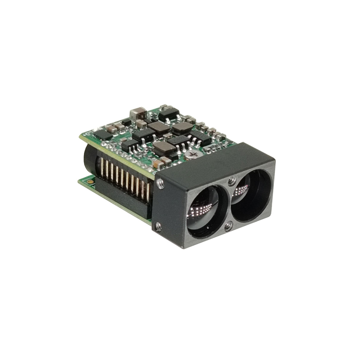
The STA-D15X miniature laser ranging module uses a 905nm semiconductor laser, which has the characteristics of long range, low power consumption, small size, and eye safety. It is very suitable for integrating small unmanned aerial vehicle pods, handheld night vision devices, thermal imaging and other equipment. Max range:1500m Ranging accuracy: ± 1m Ranging frequency: Single-shot ranging,1Hz,2Hz Weight:5g ±0.5g
Send Inquiry
Product Description
Key Features:
Semiconductor Laser Technology: Superior reliability, compactness and lower power consumption than traditional time-of-flight (TOF) rangefinders, enabling integration into portable and space-constrained devices.
Product performance index
| Serial number | Project Name | STA-D15X |
| 1 | Human eye safety | Yes |
| 2 | Laser wavelength | 905nm |
| 3 | Laser divergence angle | 1×6mrad |
| 4 | Receiving field of view | ~20mrad |
| 5 | Transmitter Caliber | Φ7mm |
| 6 | Receiving caliber | Φ7mm |
| 7 | Ranging range | 5~1500m |
| 8 | Ranging accuracy | ±1m |
| 9 | Measuring frequency | Single-shot ranging, 1Hz, 2Hz |
| 10 | Baud rate | 115200bps (Default)/9600bps/38400bps/57600bps |
| 11 | Accuracy rate | ≥98% |
| 12 | False alarm rate | ≤1% |
| 13 | Data Interface | UART(TTL_3.3V) |
| 14 | Supply voltage | DC 3~5 V |
| 15 | Power consumption | Standby power ≤ 0.6WAverage ≤ 0.8W@1HzPeak value ≤ 1.3W@1Hz |
| 16 | ||
| 17 | Starting peak current | ≤ 680mA |
| 18 | Leakage current | < 50uA |
| 19 | Weights | 5±0.5g |
| 20 | Size(L×W×H) | ≤22.5mm×16mm×9.5mm |
| 21 | Operating temperature | -20~+60℃ |
| 22 | Storage temperature | -30~+60℃ |
| 23 | Shock | 1200g, 1ms |
| 24 | Vibration | 5~50~5Hz, 1 octave/min, 2.5g |
| 25 | Reliability | MTBF≥1500h |
| 26 | Start-up time | ≤100ms; |
| 27 | Electrical interface | Connector plug: 0.8WTB-6Y-2Connector socket: 0.8WTB-6AWB-01 |
Ranging 1500m,Data testing environment with visibility ≥ 25km and humidity ≤ 50%.
Module Composition
The main components of the laser rangefinder product are as follows:
a) Receiving and transmitting components;
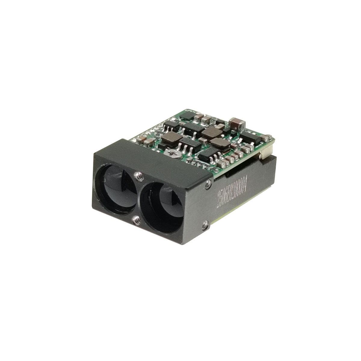
b) Circuit components;22.5mm×16mm×9.5mm(L×W×H),the weight is ≤5g±0.5g, and its appearance is shown in Fig.1.
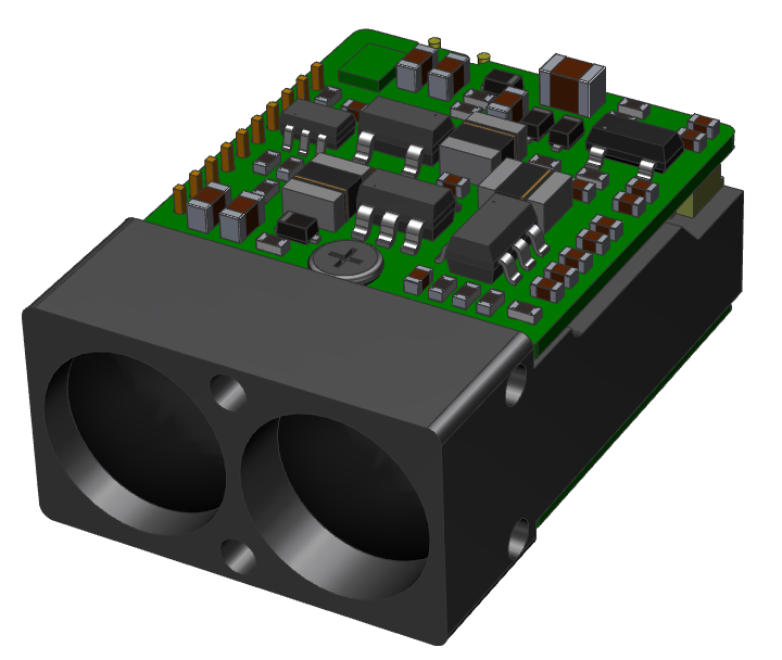
Figure 1 Product Appearance
Structure installation interface
The external dimensions of the mechanical and optical interfaces are shown in Figure 2.
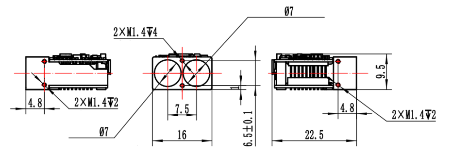
Figure 2 Mechanical and optical interface diagram
Electrical interface
Power supply voltage: 3.3V (can be biased to 3.3V~5V);
Communication type: UART-TTL (3.3V);
Peak starting current: ≤ 680mA;
Standby power consumption: ≤ 0.6W;
Average power consumption: ≤ 0.8W@1Hz ;
Peak power consumption for distance measurement: ≤ 1.35W@1Hz ;
Leakage current: < 50uA;
Power on ranging response time: ≤ 100ms
The upper computer end achieves cross-linking testing with the distance measuring machine end 0.8WTB-6AWB-01 connector (Yueqing Huabao) through the 0.8WTB-6Y-2 connector. The definitions of the power supply and communication port pins for the rangefinder are shown in the table below.
Table 2 Definition of Product Electrical Pin
| Pin | Labeling | Electrical Characteristics Definition | Signal direction |
| 1 | Power-EN | ||
| 2 | TTL_RXD | Signal input port | Host computer to rangefinder |
| 3 | TTL_TXD | Signal output port | Rangefinder to host computer |
| 4 | NC | ||
| 5 | Power supply+ | ||
| 6 | GND |

Figure 3: 1 Pin
Electrical Connection Diagram

Module Communication
Communication Interface
Baud rate: 115200bps (default)/9600bps/38400bps/57600bps;
Single byte transmission format: includes 1 start bit, 8 data bits, no checksum, 1 stop bit, 8-bit data is transmitted first to the lower bit and then to the higher bit.
Single ranging instruction
Note: Sending verification code=Byte 3+Byte 4+Byte 5+Byte 6+Byte 7;
Receive checksum=Byte 1+Byte 2+Byte 3+Byte 4+Byte 5+Byte 6+Byte 7.
Send to the Ranging module:
| byte | 1 | 2 | 3 | 4 | 5 | 6 | 7 | 8 |
| Description | 0x55 | 0xAA | 0x88 | 0xFF | 0xFF | 0xFF | 0xFF | 0x84 |
Ranging module returns
| byte | 1 | 2 | 3 | 4 | 5 | 6 | 7 | 8 |
| Description | 0x55 | 0xAA | 0x88 | status | 0xFF | DATA_H | DATA_L | verification code |
Status=0, Single measurement failed; DATA_H=0xFF,DATA_L=0xFF; status=1, Single measurement successful; DATAH_=high byte of measurement result; DATA_L=low byte of measurement result.
Continuous distance measurement instruction
Note: Sending verification code=Byte 3+Byte 4+Byte 5+Byte 6+Byte 7;
Receive checksum=Byte 1+Byte 2+Byte 3+Byte 4+Byte 5+Byte 6+Byte 7.
| byte | 1 | 2 | 3 | 4 | 5 | 6 | 7 | 8 |
| Description | 0x55 | 0xAA | Freq | 0xFF | 0xFF | 0xFF | 0xFF | verification code |
Ranging module returns
| byte | 1 | 2 | 3 | 4 | 5 | 6 | 7 | 8 |
| Description | 0x55 | 0xAA | Freq | status | 0xFF | DATA_H | DATA_L | verification code |
Status=0, Continuous measurement failure; DATA_H=0xFF,DATA_L=0xFF; status=1, Continuous measurement successful; DATAH_=high byte of measurement result; DATA_L=low byte of measurement result.
Freq=0x89, 1Hz ranging; Freq=0xB9, 5Hz ranging; Freq=0xC9, 10Hz ranging; Freq=0xF9, Axis calibration mode (sends back the axis calibration status once after receiving the calibration command).
Stop Ranking
Send to the Ranging module
| byte | 1 | 2 | 3 | 4 | 5 | 6 | 7 | 8 |
| Description | 0x55 | 0xAA | 0x8E | 0xFF | 0xFF | 0xFF | 0xFF | 0x8A |
Ranging module returns
| byte | 1 | 2 | 3 | 4 | 5 | 6 | 7 | 8 |
| Description | 0x55 | 0xAA | 0x8E | status | 0xFF | 0xFF | 0xFF | verification code |
Status=0, Failed to close continuous measurement; status=1, Close continuous measurement successfully.
Note: The data is returned in hexadecimal format, and all data results are output by multiplying the actual data by 10;
Example: dist=2000.3m, output data is 20003, converted to hexadecimal as 4E23, i.e. Data1=0x4E, Data2=0x23.
Hot Tags: 1500m Micro Laser Rangefinder Module, Manufacturers, Suppliers, Factory, China, Made in China, Customized, High Quality
Related Category
905nm Laser Range Finder Module
1535nm Laser Range Finder Module
1570nm Laser Range Finder Module
1.54um Laser Rangefinder Module
1064nm Laser Target Designator
Anti drone ststem module
Ranging Lidar Module
Send Inquiry
Please feel free to give your inquiry in the form below. We will reply you in 24 hours.


")