Home
>
Products > Laser Rangefinder Module > 905nm Laser Range Finder Module > Laser Rangefinder Module 120m 4Khz


Laser Rangefinder Module 120m 4Khz
STA-MK400 high-rate laser ranging module is a laser ranging sensor based on Time-of-Flight (TOF) technology. It features a built-in controller and ranging algorithm, with a ranging frequency of up to 4KHz and a ranging range of up to 120m. It supports UART level output communication and possesses strong anti-interference capabilities, ensuring stable operation even in sunlight.
Send Inquiry
Product Description
The MK400 features high accuracy, compact size, and lightweight. It is highly suitable for small drone systems such as altitude holding, obstacle avoidance, and cruise, as well as for system integration in autonomous vehicles.
| Basic parameters of the module | ||
| Model | STA-MK400 | |
| Ranging accuracy | ±0.1m | |
| Module size | ≤32*19*16mm | |
| range capability | Typical target | ≥300m, target reflectance 90% |
| Building survey | ≥120m | |
| Measure natural target | ≥80m | |
| Recent ranging | 0.1m | |
| Range frequency | 4KHz | |
| Resolution ratio | ±0.1m | |
| Working current | ≤200mA | |
| Standby current | ≤33mA | |
| Standby power consumption | ≤0.2W | |
| Power consumption | ≤0.6W | |
| CI | TTL | |
| Working temperature | -10℃~+55℃ | |
| Storage temperature | -20℃~+65℃ | |
| Input voltage | 5V | |
| Laser wave length | 905nm | |
| Beam divergence angle | 8 mrad | |
| Power | ≤ 1 mW safe for human eye | |
| Range finding method | impulse | |
| Weight | 7.7±0.2g | |
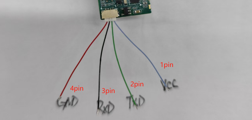
| The pin configuration of the STA-MK400 module is illustrated in the diagram below. | |||||
|
|||||
| Pin number | functional description | ||||
| 1 | VCC | ||||
| 2 | TXD | ||||
| 3 | RXD | ||||
| 4 | GND | ||||
| Pour :1. The communication interface of this module is TTL. 2.UART configuration: 1 start bit, 8 data bits, 1 stop bit, no parity check; | |||||
| DC CHARACTERISTICS | |||||
| parameter | test condition | least value | crest value | unit | |
| Operating voltage (Vin) | T=25°C | 2.5 | 5.0 | V | |
| working current (I) | stand by(T=25°C, Vin=3.0V) | - | 50.0 | mA | |
| range finding condition(T=25°C, Vin=3.0V) | - | 180.0 | mA | ||
communicating protocol
| Table 1-1: Format of the Host Computer Instruction Frame | |||||||
| Issued by the host computer | |||||||
| byte | 0 | 1 | 2 | 3 | 4 … (N - 1) | N | |
| meaning | frame header | module address | DL | command and parameter | CheckSum | ||
| numeric value | 0xA5 | 0x5A | 0 - 0xFF | LEN |
|
|
|
| Note 1: Data length refers to the number of bytes from byte 3 to N, where LEN = N-2. | |||||||
| Note 2: When the host computer sends data, the CheckSum calculation involves summing up all data (excluding the frame header) in bytes and taking the lower 8 bits, then calculating thisThe 8-bit binary complement is the CheckSum; example:The host computer sends a continuous ranging command (0x13) with module address 01 and a 3-byte data field. The CheckSum is calculated as follows:The sum of 0x01,0x03, and 0x13 equals 0x17, with the least significant bit (LSB) being 0x17. The two's complement of 0x17 is 0xE9.So CheckSum = 0xE9The actual data frame transmitted by the host computer is: A5 5A 01 03 13 E9 | |||||||
|
|
|
|
|
|
|
|
|
| Table 1-2: Format of the module output frame | |||||||
| module emission | |||||||
| byte | 0 | 1 | 2 | 3 | 4 … (N - 1) | N | |
| meaning | frame header | module address | data description | data field | CheckSum | ||
| numeric value | 0xA5 | 0x5A | 0 - 0xFF | (see note 1) |
|
|
|
| Note 1: Data descriptor description:D[7:6]:00: The following data represents distance measurements. A distance value of 0 indicates no distance was detected. 01: The subsequent data contains supplementary information, with details provided in Table 1-3. 10,11: Factory reservedD[5:0]: Data length (see Note 1 in Table 1); | |||||||
| Note 2: When the host computer receives the data, it calculates the CheckSum by summing all data from the module address to the CheckSum in bytes.Sum and the last 8 bits. Example:The module transmits the distance data 0x0B4A with address 01. The host computer receives the data frame: A5 5A 01 03 0B 4A A7Verification: The sum of 0x01,0x03,0x0B,0x4A, and 0xA7 equals 100, with the least significant bit (LSB) of the sum being 00, indicating no error. | |||||||
|
|
|
|
|
|
|
|
|
| Table 1-3 Other response information | |||||||
| Byte 4 | Byte 5 | Byte 6 | Byte 7 | Byte 8 | explain | ||
| 06 | CheckSum | not have | not have | not have | Simple response | ||
| E0 | error code | CheckSum | not have | not have | error message frame | ||
| E1 | mismark | CheckSum | not have | not have | Boot self-test error | ||
| A1 | Baud rate | CheckSum | not have | not have | Response to baud rate change | ||
| A3 | module address | CheckSum | not have | not have | Response when reading or modifying module address | ||
| AF | Software version | Product version number | CheckSum | Response when reading software version number | |||
|
|
|
|
|
|
|
||
|
|
|
|
|
|
|
||
|
Note 1: Example of software version number (2-digit sub-version): Example 1: When the software version number is 0x0064 (equivalent to 100 in decimal), the version number is V1.00. Example 2: When the software version number is 0x03F2 (equivalent to 1010 in decimal), the version number is V10.10.Product version number example (1-digit sub-version): Example 1: When the product version number is 0x0A (equivalent to 10 in decimal), the version number is V1.0. Example 2: When the product version number is 0x65 (equivalent to 101 in decimal), the version number is V10.1. |
|||||||
|
|
|
|
|
|
|
|
|
| Table 2-1: Stop Range Measurement | |||||||
| Issued by the host computer | |||||||
| byte | 0 | 1 | 2 | 3 | 4 | 5 | |
| meaning | frame header | module address | DL | instruct | CheckSum | ||
| numeric value | 0xA5 | 0x5A | 0 - 0xFF | 0x03 | 0x10 | ||
| module emission | |||||||
| byte | 0 | 1 | 2 | 3 | 4 | 5 | |
| meaning | frame header | module address | data description | data field | CheckSum | ||
| numeric value | 0xA5 | 0x5A | 0 - 0xFF | 0x43 | 06 | ||
|
|
|
||||||
| Table 2-2 Single Range Measurement | |||||||
| Issued by the host computer | |||||||
| byte | 0 | 1 | 2 | 3 | 4 | 5 | |
| meaning | frame header | module address | DL | instruct | CheckSum | ||
| numeric value | 0xA5 | 0x5A | 0 - 0xFF | 0x03 | 0x12 | ||
| module emission | |||||||
| byte | 0 | 1 | 2 | 3 | 4 | 5 | 6 |
| meaning | frame header | module address | data description | Distance data | CheckSum | ||
| numeric value | 0xA5 | 0x5A | 0 - 0xFF | 0x04 | 0 - 0xFFFF | ||
|
|
|
|
|
|
|
|
|
| Table 2-3 Continuous ranging | |||||||
| Issued by the host computer | |||||||
| byte | 0 | 1 | 2 | 3 | 4 | 5 | |
| meaning | frame header | module address | DL | instruct | CheckSum | ||
| numeric value | 0xA5 | 0x5A | 0 - 0xFF | 0x03 | 0x13 | ||
| module emission | |||||||
| byte | 0 | 1 | 2 | 3 | 4 | 5 | 6 |
| meaning | frame header | module address | data description | Distance data | CheckSum | ||
| numeric value | 0xA5 | 0x5A | 0 - 0xFF | 0x04 | 0 - 0xFFFF | ||
|
|
|
|
|
|
|
|
|
| Table 3-1: Laser Indicator Off | |||||||
| Issued by the host computer | |||||||
| byte | 0 | 1 | 2 | 3 | 4 | 5 | |
| meaning | frame header | module address | DL | instruct | CheckSum | ||
| numeric value | 0xA5 | 0x5A | 0 - 0xFF | 0x03 | 0x18 | ||
| module emission | |||||||
| byte | 0 | 1 | 2 | 3 | 4 | 5 | |
| meaning | frame header | module address | data description | data field | CheckSum | ||
| numeric value | 0xA5 | 0x5A | 0 - 0xFF | 0x43 | 06 | ||
|
|
|
|
|
|
|
|
|
|
|
|
|
|
|
|
|
|
| Table 3-2 Laser indicator on (with laser indicator) | |||||||
| Issued by the host computer | |||||||
| byte | 0 | 1 | 2 | 3 | 4 | 5 | |
| meaning | frame header | module address | DL | instruct | CheckSum | ||
| numeric value | 0xA5 | 0x5A | 0 - 0xFF | 0x03 | 0x19 | ||
| module emission | |||||||
| byte | 0 | 1 | 2 | 3 | 4 | 5 | |
| meaning | frame header | module address | data description | data field | CheckSum | ||
| numeric value | 0xA5 | 0x5A | 0 - 0xFF | 0x43 | 06 | ||
|
|
|
|
|
|
|
|
|
| Table 4-1: Peripheral Circuit Switch | |||||||
| Issued by the host computer | |||||||
| byte | 0 | 1 | 2 | 3 | 4 | 5 | |
| meaning | frame header | module address | DL | instruct | CheckSum | ||
| numeric value | 0xA5 | 0x5A | 0 - 0xFF | 0x03 | 0x1A | ||
| module emission | |||||||
| byte | 0 | 1 | 2 | 3 | 4 | 5 | |
| meaning | frame header | module address | data description | data field | CheckSum | ||
| numeric value | 0xA5 | 0x5A | 0 - 0xFF | 0x43 | 06 | ||
|
|
|
|
|
|
|
|
|
| Table 4-2: Peripheral Circuit Open | |||||||
| Issued by the host computer | |||||||
| byte | 0 | 1 | 2 | 3 | 4 | 5 | |
| meaning | frame header | module address | DL | instruct | CheckSum | ||
| numeric value | 0xA5 | 0x5A | 0 - 0xFF | 0x03 | 0x1B | ||
| module emission | |||||||
| byte | 0 | 1 | 2 | 3 | 4 | 5 | |
| meaning | frame header | module address | data description | data field | CheckSum | ||
| numeric value | 0xA5 | 0x5A | 0 - 0xFF | 0x43 | 06 | ||
| Note: Disabling peripheral circuits reduces power consumption, but may cause a delay in the initial ranging response time. | |||||||
|
|
|
|
|
|
|
|
|
| Table 5-1: Modification of the baud rate | |||||||
| Issued by the host computer | |||||||
| byte | 0 | 1 | 2 | 3 | 4 | 5 | 6 |
| meaning | frame header | module address | DL | instruct | parameter | CheckSum | |
| numeric value | 0xA5 | 0x5A | 0 - 0xFF | 0x04 | 0x20 | new port rate | |
| module emission | |||||||
| byte | 0 | 1 | 2 | 3 | 4 | 5 | 6 |
| meaning | frame header | module address | data description | frame type | parameter | CheckSum | |
| numeric value | 0xA5 | 0x5A | 0 - 0xFF | 0x44 | 0xA1 | new port rate | |
| Note: The new baud rate requires a system reboot to take effect. | |||||||
|
|
|
|
|
|
|
|
|
| Table 5-2 | |||||||
| Baud rate: 460800, Module address: 0x00 | |||||||
|
|
|
|
|
|
|
|
|
| Table 6-1: Modified module addresses | |||||||
| Issued by the host computer | |||||||
| byte | 0 | 1 | 2 | 3 | 4 | 5 | 6 |
| meaning | frame header | module address | DL | instruct | New address | CheckSum | |
| numeric value | 0xA5 | 0x5A | 0 - 0xFF | 0x04 | 0x22 | 0 - 0xFF | |
| module emission | |||||||
| byte | 0 | 1 | 2 | 3 | 4 | 5 | 6 |
| meaning | frame header | module address | data description | frame type | New address | CheckSum | |
| numeric value | 0xA5 | 0x5A | 0 - 0xFF | 0x44 | 0xA3 | 0 - 0xFF | |
| Note 1: The new module address takes effect immediately. | |||||||
| Note 2: Address 0xFF is a broadcast address; | |||||||
|
|
|
|
|
|
|
|
|
| Table 6-2 Read module address | |||||||
| Issued by the host computer | |||||||
| byte | 0 | 1 | 2 | 3 | 4 | 5 | |
| meaning | frame header | module address | DL | instruct | CheckSum | ||
| numeric value | 0xA5 | 0x5A | 0 - 0xFF | 0x03 | 0x23 | ||
| module emission | |||||||
| byte | 0 | 1 | 2 | 3 | 4 | 5 | 6 |
| meaning | frame header | module address | data description | frame type | New address | CheckSum | |
| numeric value | 0xA5 | 0x5A | 0 - 0xFF | 0x44 | 0xA3 | 0 - 0xFF | |
|
|
|
|
|
|
|
|
|
| Table 7-1 Software Version | |||||||
| Issued by the host computer | |||||||
| byte | 0 | 1 | 2 | 3 | 4 | 5 | |
| meaning | frame header | module address | DL | instruct | CheckSum | ||
| numeric value | 0xA5 | 0x5A | 0 - 0xFF | 0x03 | 0x2F | ||
| module emission | |||||||
| byte | 0 | 1 | 2 | 3 | 4 | 5、6、7 | 8 |
| meaning | frame header | module address | data description | frame type | version number | CheckSum | |
| numeric value | 0xA5 | 0x5A | 0 - 0xFF | 0x46 | 0xAF | See note 1-3 in Table 1 | |
Hot Tags: Laser Rangefinder Module 120m 4Khz, Manufacturers, Suppliers, Factory, China, Made in China, Customized, High Quality
Related Category
905nm Laser Range Finder Module
1535nm Laser Range Finder Module
1570nm Laser Range Finder Module
1.54um Laser Rangefinder Module
1064nm Laser Target Designator
Anti drone ststem module
Ranging Lidar Module
Send Inquiry
Please feel free to give your inquiry in the form below. We will reply you in 24 hours.


")